
ITERATIVE MMSE DETECTION FOR MIMO/BLAST DS-CDMA
SYSTEMS IN FREQUENCY SELECTIVE FADING CHANNELS
Achieving High Performance in Fully Loaded Systems
João Carlos Silva, Nuno Souto, Francisco Cercas
Instituto Superior Técnico/IT, Torre Norte 11-11, Av. Rovisco Pais 1, 1049-001 Lisboa, Portugal
Rui Dinis
CAPS, Av. Rovisco Pais 1,1049-001 Lisboa, Portugal
Keywords: MIMO-BLAST, Iterative Interference Canceller, W-CDMA.
Abstract: A MMSE (Minimum Mean Square Error) DS-CDMA (Direct Sequence-Code Division Multiple Access)
receiver coupled with a low-complexity iterative interference suppression algorithm was devised for a
MIMO/BLAST (Multiple Input, Multiple Output / Bell Laboratories Layered Space Time) system in order
to improve system performance, considering frequency selective fading channels. The scheme is compared
against the simple MMSE receiver, for both QPSK and 16QAM modulations, under SISO (Single Input,
Single Output) and MIMO systems, the latter with 2Tx by 2Rx and 4Tx by 4Rx (MIMO order 2 and 4
respectively) antennas. To assess its performance in an existing system, the uncoded UMTS HSDPA (High
Speed Downlink Packet Access) standard was considered.
1 INTRODUCTION
MIMO systems have been considered to be one of
the most significant technical breakthroughs in
modern communications, since they can augment
significantly the system capacity, by increasing the
number of both transmit and receive antennas
(Foschini, 1998). Just a few years after its invention
the technology is already part of the standards for
wireless local area networks (WLAN), third-
generation (3G)
networks and beyond.
The receiver for such a scheme is obviously
complex; due to the number of antennas, users and
multipath components, the performance of a simple
RAKE/ MF (Matched Filter) receiver (or enhanced
schemes based on the MF) has a severe interference
canceling limitation, that does not allow for the
system to perform at full capacity. Therefore, a
MMSE receiver (Latva-aho, 2000), adapted for
multipath MIMO, was developed for such cases
acting as an equalizer, yielding interesting results. In
order to further augment the MMSE receiver’s
performance, an additional low complexity block
performing interference suppression was added.
Although the MMSE guarantees the minimum
variance estimates, some estimates may exceed the
threshold value in which they are supposed to be.
The interference suppression block has a built-in
SDD (Soft Decision Device), so that the initial
estimates are adjusted in order to minimize their
mean square error. The new estimates are then
introduced in a iterative Parallel Interference
Canceller (PIC) based solely on low complexity
matched-filtering, so that a new solution is found
within the imposed constraints. Such a scheme
produces a performance improvement with little
added complexity, when compared to the simple
MMSE decoder.
The structure of the paper is as follows. In
Section II, the MMSE receiver for MIMO with
multipath is introduced. The simulation setup is
detailed and results are discussed in Section III. The
main conclusions are drawn in Section IV.
54
Silva J., Souto N., Cercas F. and Dinis R. (2005).
ITERATIVE MMSE DETECTION FOR MIMO/BLAST DS-CDMA SYSTEMS IN FREQUENCY SELECTIVE FADING CHANNELS - Achieving High
Performance in Fully Loaded Systems.
In Proceedings of the Second International Conference on e-Business and Telecommunication Networks, pages 55-60
DOI: 10.5220/0001408400550060
Copyright
c
SciTePress

2 MMSE RECEIVER
A standard model for a DS-CDMA system with K
users (assuming 1 user per physical channel) and L
propagation paths is considered. The modulated
symbols are spread by a Walsh-Hadamard code with
length equal to the Spreading Factor (SF). The signal
on a MIMO-BLAST system with N
TX
transmit and
N
RX
receive antennas, at one of the receiver’s
antennas, can be expressed as:
()
1,,,, ,
1 111
() () ( ) ()
TX
N
NKL
n
RX ktx ktx ktxrx k kl
ntxk l
tttnTt
τ
=
====
=−−+
∑∑∑∑
v
rAbcsn
where N is the number of received symbols,
,ktx k
E=A
, E
k
is the energy per symbol, K is the
number of users,
()
,
n
ktx
b
is the n-th transmitted data
symbol of user k and transmit antenna tx, s
k
(t) is the
k-th user’s signature signal (equal for all antennas), T
denotes the symbol interval, n(t) is a complex zero-
mean AWGN (Additive White Gaussian Noise) with
variance
2
σ
,
()
,, ,,, ,
1
() ( )
L
n
ktxrx ktxrxl kl
l
tt
δ
=
=−
∑
cc
τ
is the impulse response of the k
-
th user’s radio
channel, c
k,tx,rx,l
is the complex attenuation factor of
the k-ths user’s l-th path of the link between the tx-th
and rx-th antenna and
,kl
τ
is the propagation delay
(assumed equal for all antennas).
Using matrix algebra, the received signal can be
represented as
v
=+r SCAb n
,
where S, C and A are the spreading, channel and
amplitude matrices respectively.
The spreading matrix S has dimensions
()()
R
X MAX RX RX
SF N N N K L N N
ρ
⋅⋅ + ⋅ × ⋅⋅⋅
(ρ
max
is
the maximum delay of the channel’s impulse
response, normalized to number of chips, and SF is
the Spreading Factor), and is composed of sub-
matrices S
RX
in its diagonal for each receive
antenna
RX
RX,1 RX,N
=diag( , , )KSS S
. Each of
these sub-matrices has
dimensions
(
)
(
)
MAX
SF N K L N
ρ
⋅+ × ⋅⋅
, and are further
composed by smaller matrices S
L
n
, one for each bit
position, with size
(
)
(
)
MAX
SF K L
ρ
+
×⋅
. The
S
RX
matrix structure is made of
RX SRX,1 SRX,N
=,,
⎡⎤
⎣⎦
KSS S , with
( )() ( )()
L
SRX,n n
SF ( 1) K L SF (N-n) K L
=0 ; ;0
n⋅−× ⋅ ⋅ × ⋅
⎡⎤
⎣⎦
SS
The S
L
matrices are made of
K
L⋅ columns;
L
n col(k=1,l=1),n col(k=1,l=L),n col(k=K,l=L),n
=,,,,
⎡
⎤
⎣
⎦
KKSS S S
.
Each of these columns is composed of
()
()
()
col( ), 1
1 delay( )
1delay()
=0 , () ,0
MAX
T
kl n n SF
l
l
k
ρ
×
×
×−
⎡
⎤
⎣
⎦
Ssp
, where sp
n
(k) is the combined spreading &
scrambling for the bit n of user k.
These S
L
matrices are either all alike if no long
scrambling code is used, or different if the
scrambling sequence is longer than the SF. The S
L
matrices represent the combined spreading and
scrambling sequences, conjugated with the channel
delays. The shifted spreading vectors for the
multipath components are all equal to the original
sequence of the specific user.
1,1,1, ,1,1,
1,1, , ,1, ,
1, ,1, , ,1,
1, , , , , ,
nKn
Ln K Ln
L
n
SF n K SF n
SF L n K SF L n
⎡
⎤
⎢
⎥
⎢
⎥
=
⎢
⎥
⎢
⎥
⎢
⎥
⎣
⎦
LL
MO L MO
ML M
OLLO
SS
SS
S
SS
SS
Note that, in order to correctly model the
multipath interference between symbols, there is an
overlap between the S
L
matrices, of ρ
MAX
.
The channel matrix C is a
(
)
(
)
RX TX
KLNN KN N
⋅
⋅⋅ × ⋅ ⋅
matrix, and is
composed of N
RX
sub-matrices, each one for a receive
antenna
RX
RR
,1 RX ,N
=;;
RX
⎡
⎤
⎣
⎦
KCC C
. Each C
R
matrix
is composed of N C
KT
matrices alongside its
diagonals.
RX
1,1
R
,1
,1
1,
R
RX,N
,
RX
RX
KT
RX
KT
N
KT
N
KT
NN
⎡
⎤
⎡⎤
⎢
⎥
⎢⎥
=
⎢
⎥
⎢⎥
⎢
⎥
⎢⎥
⎣⎦
⎢
⎥
=
⎢
⎥
⎢
⎥
⎡
⎤
⎢
⎥
⎢
⎥
⎢
⎥
=
⎢
⎥
⎢
⎥
⎢
⎥
⎢
⎥
⎣
⎦
⎣
⎦
O
M
O
C
C
C
C
C
C
C
Each C
KT
matrix is
()( )
TX
KL KN⋅×⋅
, and
represents the fading coefficients for the current
symbol of each path, user, transmit antenna and
receive antenna. The matrix structure is made up of
further smaller matrices alongside the diagonal of
C
KT
,
(
)
,1 ,
=diag , ,
KT T T
K
KK
KCCC
, with C
T
of
dimensions
TX
L
N
×
, representing the fading
coefficients for the user’s multipath and tx-th antenna
component.
1,1,1 ,1,1
1, ,1 , ,1
1,1, ,1,
1, , , ,
TX
TX
TX
TX
N
LNL
KT
KNK
LK N LK
⎡
⎤
⎢
⎥
⎢
⎥
⎢
⎥
⎢
⎥
=
⎢
⎥
⎢
⎥
⎢
⎥
⎢
⎥
⎢
⎥
⎣
⎦
L
MM
L
O
L
MM
L
CC
CC
C
CC
CC
ITERATIVE MMSE DETECTION FOR MIMO/BLAST DS-CDMA SYSTEMS IN FREQUENCY SELECTIVE FADING
CHANNELS - Achieving High Performance in Fully Loaded Systems
55

The A matrix is a diagonal matrix of
dimension
()
TX
KN N⋅⋅
, and represents the amplitude
of each user per transmission antenna and symbol,
()
1,1,1 ,1,1 , ,1 , ,
=diag , , , , , ,
TX TX TX
NNKNKN
KK KAAA A A
.
The matrix resultant from the SCA operation
(henceforth known as SCA matrix) is depicted in
Figure 1. It is a
()
TX RX MAX
NKNN NSF
ρ
⋅⋅× ⋅ ⋅ +
matrix,
and is the reference matrix for the decoding
algorithms.
Figure 1 : Layout of the SCA matrix
Vector b represents the information symbols. It
has length
(
)
TX
KN N⋅⋅
, and has the following
structure
1,1,1 ,1,1 1, ,1 , ,1 , ,
=,, ,,,, ,,
TX TX TX
T
N K NK NKN
⎡⎤
⎣⎦
KKK Kbb b b b b
.
Note that the bits of each transmit antenna are
grouped together in the first level, and the bits of
other interferers in the second level. This is to
guarantee that the resulting matrix to be inverted has
all its non-zeros values as close to the diagonal as
possible. Also note that there is usually a higher
correlation between bits from different antennas
using the same spreading code, than between bits
with different spreading codes.
Finally, the n vector is a
(
)
R
XRXMAX
NSFN N
ρ
⋅⋅ + ⋅
vector with noise
components to be added to the received vector r
v
,
which is partitioned by N
RX
antennas,
1,1,1 1, ,1 ,1,1 , ,1 ,1, , ,
=,,,,,, ,, ,,
MAX RX MAX RX
T
vSFNNSFNNNSFN
ρρ
++
⎡⎤
⎣⎦
KKK K Krr r r r r r
(note that the delay ρ
MAX
is only contemplated in the
final bit, though its effects are present throughout r
v
).
The MMSE algorithm yields the symbol
estimates,
()
1
M
MSE M MF
−
=yEy
Where y
MF
is the (un-normalized) matched filter
output
()
H
MF
=
v
ySCAr
and the E
M
is the Equalization Matrix (cross-
correlation matrix of the users’ signature sequences
after matched filtering, at the receiver)
2
M
σ
=+
E
RI
with
HH
=
×××××R
and
2
σ
as the noise variance of n.
The configuration is done in such a way that the
E
M
presents itself as if the Sparse Reverse Cuthill-
McKee ordering algorithm (Liu, 1981) had been
applied to it, and thus there is no fill-in when
performing the E
M
inverse using the Choleski
algorithm. The expected main problem associated
with such scheme is the size of the matrices, which
assume huge proportions. This has been the main
perceived drawback of such scheme, responsible for
the reduced amount of work of MMSE-based
schemes in MIMO and frequency selective channels.
However, if the sparseness of the matrices is taken
into account, only a fraction of the memory and
computing power is required.
The Enhanced-MMSE (E-MMSE) receiver adds
a PIC after the MMSE algorithm. The cancelling
algorithm consists of removing the estimated
interference from the matched filter result. The initial
estimate is obtained from the MMSE result.
()
2
1
,
M
MSE estim
SDD
σ
= y
where
2
M
MSE
σ
is the noise variance of
M
MSE
y
.
The cancellation operates on the MF result, and is
simply the simultaneous removal of all influences
that the symbols have on each other, throughout the
transmission and receiver operations, in the absence
of noise (accomplished with the removal of the main
diagonal of R)
()
()
1nn
MF
diag
+
=−−yR R
The result is then normalized and passed through
the SDD, becoming the estimate for the next
iteration
2
11
,
nn
NORM MMSE
SDD
σ
++
⎛⎞
=
⎜⎟
⎝⎠
e C
where
e represents element-wise
multiplication. The normalization consists simply of
inverting the main diagonal of R,
()
1
NORM
diag
−
=cR
, so as to compensate for the
spreading, amplitude, channel power and cross-
correlation between symbols. The function sdd() is
the soft decision device function and diag() refers to
all the elements in the diagonal of a matrix. Note
that the initial MMSE output does not need any
normalization, since this is accomplished by the
equalization from the E
M
.
ICETE 2005 - WIRELESS COMMUNICATION SYSTEMS AND NETWORKS
56
The SDD is based on the assumption that the
remaining noise in the estimates is essentially
AWGN (Divsalar, 1998), being taken as optimum
under this assumption. Taking x as either the real or
imaginary component of the symbol, and considering
that the real and imaginary part of the QPSK
constellation both consist of {-1,1}, the SDD for the
QPSK modulation is given by
2
tan h
x
x
y
σ
⎛⎞
=
⎜⎟
⎝⎠
.
Applying the same reasoning for the 16QAM
case (assuming that the real/imaginary constellation
components point have values of {-3,-1,1,3}), we get
2
2
4
22
4
22
3
3 sin h sin h
3
cosh cosh
xx
xx
x
x
e
y
x
x
e
σ
σ
σ
σ
σσ
−
−
⎛⎞ ⎛⎞
+
⎜⎟ ⎜⎟
⎝⎠ ⎝⎠
=
⎛⎞ ⎛⎞
+
⎜⎟ ⎜⎟
⎝⎠ ⎝⎠
where
2
x
σ
is the noise power of each
real/imaginary component of the symbol prior to
SDD.
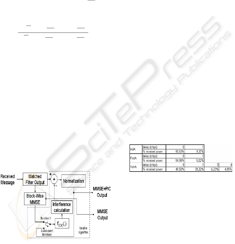
Figure 2 illustrates the PIC. The added complexity
to the MMSE algorithm is negligible since the main
system matrices (S,C,A,R) required by the PIC have
already been computed for the MMSE operation. The
iterative algorithm only needs to multiply the current
estimated symbol by pre-defined matrices, while
performing the SDD. The main difference from the
PIC structure shown to conventional PIC schemes is
the fact that this new scheme makes use of the
MMSE’s structure and thus is able to correctly
estimate the interference caused by ISI (Inter-
Symbolic Interference) and MAI (Multiple Access
Interference), aside the thermal noise component.
The used normalization factor is also improved since,
besides containing the effect of spreading and
channel power, it contains the cross-correlation
effects caused by multipath, which in conventional
receivers isn’t used.
Figure 2 : PIC Structure
3 SIMULATION SETUP &
RESULTS
This work was inspired on the uncoded 3G HSDPA
standard, and thus considers a SF=16 using
Hadamard codes, QPSK and 16QAM modulation, a
chip rate of 3.84 Mcps and a Gold-sequence
scrambling code. Each TX antenna can thus host a
maximum of 16 physical channels. One user per
physical channel is assumed. Simulations were run
for SISO and MIMO orders 2 and 4, so that all the
expected future UE types were covered. Minimum
and full loading (0 and 15 interferers per transmit
antenna respectively, assuming that the main user is
using the first physical channel of each antenna) was
considered. The E-MMSE scheme used cancellation
of two iterations after the MMSE decoding. Blocks
of 1024 bits per physical channel per antenna were
used.
The main UMTS channels, namely Indoor A,
Pedestrian A and Vehicular A (taken from (3GPP TR
25.943)) were simulated. Since only 1 sample per
chip was used in the simulations, the channels were
adjusted to the chip delay time of 260ns, using the
constant mean delay spread method (Silva, 2003).
For the particular case of Vehicular A, since the
method yields 8 taps, with the last ones having low
power levels, an adjustment was made so that only
the main taps were considered. The resulting
channels are depicted in Figure 3. The considered
velocities were 50km/h for Vehicular A and 3km/h
for the remaining channels.
Figure 3 : Resulting UMTS channels
The Monte Carlo method was employed for the
simulations. All results were portrayed for received
E
b
/N
0
values vs BER (Bit Error Rate). For the sake of
comparison, we also considered the simple MMSE
receiver.
Based on the results of figure 4, only two PIC
iterations are needed to achieve the best results; all
results in the posterior figures thus consider only two
iterations for the E-MMSE scheme.
In figures 5-8, the E-MMSE results for different
MIMO orders, channels, modulations and loadings
can be observed. The performance curves are parallel
to the MMSE results, though a little deviated to the
left; i.e. there is an offset of the curves corresponding
to the performance gain over MMSE. Figures 9-11
ITERATIVE MMSE DETECTION FOR MIMO/BLAST DS-CDMA SYSTEMS IN FREQUENCY SELECTIVE FADING
CHANNELS - Achieving High Performance in Fully Loaded Systems
57
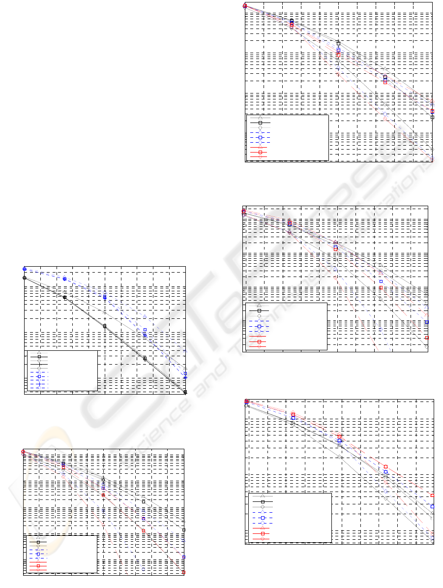
compare some of the results of the E-MMSE to the
simple MMSE algorithm.
For the SISO case without interference, there is a
negligible difference between the E-MMSE and
MMSE. This was expected, since the canceller is
only rearranging the results so that the estimates
symbols do not exceed their thresholds. For the
MIMO 2x2 case without interference, differences
between 1dB and 2dB can be found between
channels and modulations, with the biggest
differences being registered for QPSK modulations
(due to smaller probabilities of bit errors, and thus
having a very small error propagation in the
canceling algorithm).
In the full loading scenario (15 interferers),
differences over 5dB and 3dB can be found for
QPSK and 16QAM respectively. The differences are
greater than for the case of minimum loading, due to
the PIC canceling interference from other users, thus
being more effective.
3.1 E-MMSE Results
0 2 4 6 8 10 12 14 16 18 20
10
-3
10
-2
10
-1
E
b
/N
0
(dB)
BER
No Iterations, QPSK
1 Iteration, QPSK
2 Iteration, QPSK
3 Iterations, QPSK
4 Iterations, QPSK
No Iterations, 16QAM
1 Iteration, 16QAM
2 Iteration, 16QAM
3 Iterations, 16QAM
4 Iterations, 16QAM
Figure 4 : BER performance for E-MMSE, Vehicular A
channel, MIMO 2x2, 15 interferers - effect on number of
cancelling stages.
0 2 4 6 8 10 12 14 16 18 20
10
-5
10
-4
10
-3
10
-2
10
-1
E
b
/N
0
(dB)
BER
1TX1RX, Pedestrian A
1TX1RX, Indoor A
1TX1RX, Vehicular A
2TX2RX, Pedestrian A
2TX2RX, Indoor A
2TX2RX, Vehicular A
4TX4RX, Pedestrian A
4TX4RX, Indoor A
4TX4RX, Vehicular A
Figure 5 : E-MMSE scheme – QPSK modulation, 0
interferers
0 2 4 6 8 10 12 14 16 18 20
10
-4
10
-3
10
-2
10
-1
E
b
/N
0
(dB)
BER
1TX1RX, Pedestrian A
1TX1RX, Indoor A
1TX1RX, Vehicular A
2TX2RX, Pedestrian A
2TX2RX, Indoor A
2TX2RX, Vehicular A
4TX4RX, Pedestrian A
4TX4RX, Indoor A
4TX4RX, Vehicular A
Figure 6 : E-MMSE scheme – QPSK modulation, 15
interferers
2 4 6 8 10 12 14 16 18 20
10
-4
10
-3
10
-2
10
-1
E
b
/N
0
(dB)
BER
1TX1RX, Pedestrian A
1TX1RX, Indoor A
1TX1RX, Vehicular A
2TX2RX, Pedestrian A
2TX2RX, Indoor A
2TX2RX, Vehicular A
4TX4RX, Pedestrian A
4TX4RX, Indoor A
4TX4RX, Vehicular A
Figure 7 : E-MMSE scheme – 16QAM modulation, 0
interferers
2 4 6 8 10 12 14 16 18 20
10
-3
10
-2
10
-1
E
b
/N
0
(dB)
BER
1TX1RX, Pedestrian A
1TX1RX, Indoor A
1TX1RX, Vehicular A
2TX2RX, Pedestrian A
2TX2RX, Indoor A
2TX2RX, Vehicular A
4TX4RX, Pedestrian A
4TX4RX, Indoor A
4TX4RX, Vehicular A
Figure 8 : E-MMSE scheme – 16QAM modulation, 15
interferers
ICETE 2005 - WIRELESS COMMUNICATION SYSTEMS AND NETWORKS
58
3.2 E-MMSE vs MMSE Comparison
0 2 4 6 8 10 12 14 16 18 20
10
-4
10
-3
10
-2
10
-1
E
b
/N
0
(dB)
BER
1TX1RX, 0 interferers, E-MMSE
1TX1RX, 0 interferers, MMSE
2TX2RX, 0 interferers, E-MMSE
2TX2RX, 0 interferers, MMSE
2TX2RX, 15 interferers, E-MMSE
2TX2RX, 15 interferers, MMSE
4TX4RX, 15 interferers, E-MMSE
4TX4RX, 15 interferers, MMSE
Figure 9 : E-MMSE vs MMSE scheme – QPSK
modulation, Pedestrian A channel
0 2 4 6 8 10 12 14 16 18 20
10
-4
10
-3
10
-2
10
-1
E
b
/N
0
(dB)
BER
1TX1RX, 0 interferers, E-MMSE
1TX1RX, 0 interferers, MMSE
2TX2RX, 0 interferers, E-MMSE
2TX2RX, 0 interferers, MMSE
2TX2RX, 15 interferers, E-MMSE
2TX2RX, 15 interferers, MMSE
4TX4RX, 15 interferers, E-MMSE
4TX4RX, 15 interferers, MMSE
Figure 10 : E-MMSE vs MMSE scheme – QPSK
modulation, Vehicular A channel
2 4 6 8 10 12 14 16 18 20
10
-6
10
-5
10
-4
10
-3
10
-2
10
-1
E
b
/N
0
(dB)
BER
1TX1RX, 0 interferers, E-MMSE
1TX1RX, 0 interferers, MMSE
2TX2RX, 0 interferers, E-MMSE
2TX2RX, 0 interferers, MMSE
2TX2RX, 15 interferers, E-MMSE
2TX2RX, 15 interferers, MMSE
4TX4RX, 15 interferers, E-MMSE
4TX4RX, 15 interferers, MMSE
Figure 11 : E-MMSE vs MMSE scheme – 16QAM
modulation, Vehicular A channel
4 CONCLUSIONS
In this work, an iterative PIC was added to a MIMO-
BLAST MMSE receiver considering frequency-
selective fading channels, using the same structure as
that required by the MMSE. The used PIC is able to
cancel out most of the interference caused by
multipath, cross-correlation between users/antennas
and thermal noise. It was shown that with a small
increase in complexity, gains over 5dB and 3dB can
be achieved for QPSK and 16QAM respectively, in
what is considered one of the best joint-detection
receiver algorithms presently.
ACKNOWLEDGEMENTS
This paper was elaborated within the B-BONE
(Broadcasting and Multicasting over Enhanced
UMTS Mobile Broadband Networks) project, and
was partially funded by the Foundation of Science
and Technology (FCT), of the Portuguese Ministry of
Education.
REFERENCES
G. J. Foschini and M. J. Gans, “On limits of wireless
communications in a fading environment when using
multiple antennas,” Wireless Pers. Commun., vol. 6,
pp. 311–335, Mar. 1998.
M. Latva-aho, M. Juntti, "LMMSE Detection for DS-
CDMA Systems in Fading Channels", IEEE
Transactions on Communications, vol.48, no2,
February 2000.
George, Alan and Joseph Liu, Computer Solution of Large
Sparse Positive Definite Systems, Prentice-Hall, 1981.
D. Divsalar, M. Simon and D. Raphaeli, “ Improved
Parallel Interference Cancellation in CDMA”, IEEE
Trans. Commun. Vol.46, pp.258-268, February 1998.
3GPP, Deployment aspects, 3GPP TR 25.943 v5.1.0,
Sophia Antipolis, France, 2002.
J. C. Silva, N. Souto, A. Rodrigues, F. Cercas and A.
Correia, “Conversion of reference tapped delay line
channel models to discrete time channel models“,
VTC03 Fall, Orlando, Florida, 6-9 Oct. 2003.
ITERATIVE MMSE DETECTION FOR MIMO/BLAST DS-CDMA SYSTEMS IN FREQUENCY SELECTIVE FADING
CHANNELS - Achieving High Performance in Fully Loaded Systems
59
