
A FRAMEWORK FOR IDENTIFYING ARCHITECTURAL
PATTERNS FOR E-BUSINESS APPLICATIONS
Feras T. Dabous
1
, Fethi A. Rabhi
1
and Tariq Al-Naeem
2
1
School of Information Systems, Technology and Management
2
School of Computer Science and Engineering
The University of New South Wales, 2052 Sydney NSW, Australia
Keywords:
Patterns, e-Business Applications, Architectural Design, Legacy Systems, e-Finance.
Abstract:
The success of today’s enterprises is critically dependant on their ability to automate the way they conduct
business with customers and other enterprises by means of e-business applications. Legacy systems are valu-
able assets that must play an important role in this process. Selecting the most appropriate architectural design
for an e-business application would have critical impact on participating enterprises. This paper discusses
an initiative towards a systematic framework that would assist in identifying a range of possible alternative
architectural designs for such applications and how some of these alternatives can evolve into formal archi-
tectural patterns or anti-patterns. This paper focuses on e-business applications with some requirements and
assumptions that are often presented in a few specific domains such as e-finance. The concepts presented in
this paper are demonstrated using a real life case study in the domain of e-finance and in particular capital
markets trading.
1 INTRODUCTION
The concept of e-business applications has been used
extensively in the literature to refer to a range of ap-
plications. This range encompasses B2C interactions
(e.g. simple Web-based client/server applications)
and B2B interactions either as a workflow by means
of workflow technology or as a distributed application
by means of middleware technologies. In this paper,
we consider an e-business application domain that can
be improved by developing or utilising corresponding
business logic and functionality that can span differ-
ent organisational legacy systems.
In previous work, we identified and formalised a
number of architectural patterns based on practical
experience in the domain of e-finance. These patterns
address a similar problem context and therefore con-
stitute alternative architectures where the selection of
the most appropriate pattern is based on the prob-
lem context specification. In (Dabous et al., 2005),
we presented models for patterns qualities estimations
that can be used in the selection process for a given
problem context, whereas in (Al-Naeem et al., 2005b)
we utilised AHP (Anderson et al., 2002) method for
this selection process that is extended in (Dabous,
2005) to encompass estimations provided by the qual-
ity models.
This paper extends upon the previous work by
proposing a framework for identifying patterns that
can be used in the architectural design of e-business
applications. We consider e-business domains that
have special requirements and assumptions mainly re-
lated to the existence of legacy functionality. These
domains, such as e-finance, consist of applications
that are business process intensive and therefore we
alternatively use the term Business Process (BP) to
refer to an e-business application.
This paper is organised as follows. Section 2
presents the basic assumptions made in this research
and formalises the concepts used. It also presents e-
finance particularly capital markets as a real-life ap-
plication domain. Section 3 discusses a common ar-
chitectural description that forms the basis of the pat-
terns identification framework. Section 4 discusses
the two major phases in the proposed patterns identi-
fication framework. Section 5 presents and discusses
five design strategies that ingrain the basic input for
the framework. Section 6 presents five candidate pat-
terns that are the outcome of the first phase in the
proposed framework together with the instantiation of
each pattern on the selected application domain. Fi-
nally, section 7 concludes this paper.
88
T. Dabous F., A. Rabhi F. and Al-Naeem T. (2005).
A FRAMEWORK FOR IDENTIFYING ARCHITECTURAL PATTERNS FOR E-BUSINESS APPLICATIONS.
In Proceedings of the First International Conference on Web Information Systems and Technologies, pages 88-95
DOI: 10.5220/0001234000880095
Copyright
c
SciTePress

2 BASIC ASSUMPTIONS AND
CONCEPTS
This section presents the basic assumptions made in
this paper and introduces the different concepts used
such as functionality, legacy systems and BPs to-
gether with a selected application domain. The as-
sumptions and concepts discussed are based on sev-
eral architectural analysis, benchmarking studies, and
e-business applications development such as (Rabhi
et al., 2003) that have been conducted on a number of
legacy systems.
2.1 Review of notation
A functionality in the context of this research refers to
an identified autonomous task that resides within an
“encapsulating entity”. A functionality corresponds
to an activity within a BP which performs a specific
job (i.e. in part of the business logic). A functionality
can be either automated or new (i.e. non-automated).
If it is automated then the encapsulating entity can
be a legacy system. On the other hand, if it is new
functionality then the encapsulating entity can be a
human process. We use the notion F
all
= {f
i
: 1 ≤
i ≤ |F
all
|} to represent the set of all functionalities
(automated and not automated) that belong to a par-
ticular domain. The definition of the set F
all
does not
tell anything about the automation of any function-
ality. We also use the concept of “equivalent func-
tionalities” to refer to a group of functionalities that
have similar business logic each of which resides in
a different encapsulating entity. We use the notion
Q = {q
i
: 1 ≤ i ≤ |Q|} to represent the set of all
groups of equivalent functionalities. Each q
i
⊆ F
all
is the ı
th
set of a number of equivalent functionali-
ties such that |q
i
| ≥ 1 and q
a
∩ q
b
= φ : a 6= b and
q
i=1
q
i
= F
all
Two assumptions related to the legacy systems are
made. The first one is that each legacy system is
owned by one company within the domain of study
and their development teams are not related to the
BPs development team. The second one is that the
development team for the BPs can only interact with
these legacy systems through their defined interfaces
(e.g. in the form of APIs) and has no access permis-
sion to the corresponding source code. Therefore, we
assume that different functionalities within the same
legacy system have similar interfacing mechanism.
We use the notation F
au
⊆ F
all
to represent the
set of all automated functionalities contained in the
legacy systems of a particular domain. Let LG = {l
i
:
1 ≤ i ≤ |LG|} be the set of key legacy systems iden-
tified in that particular domain. Every l
i
⊆ F
au
and
l
a
∩ l
b
= φ when a 6= b . It is also important to note
that in practice there is no instance of two equivalent
functionalities within the same legacy system mean-
ing that if f
x
∈ l
i
and, f
y
∈ l
i
then {f
x
, f
y
} * q∀q ∈ Q.
We also consider a fixed number of BPs in a par-
ticular domain referred to by the set BP = {bp
i
: 1 ≤
i ≤ |BP |}. We assume that these BPs may have ac-
tivities that correspond to existing functionalities in
the legacy systems. The business logic of each bp
i
is expressed in terms of an activity diagram whose
nodes are the activities (i.e. functionalities) and the
arcs determines the execution flow between the func-
tionalities. We use the function activ ities(bp) ⊆ F
all
to identify the set of functionalities that are required
by the BP bp (i.e. it returns the set of all nodes in a
bp’s activity diagram).
In the context of this research we assume that
every f ∈ F
all
has at least one corresponding bp ∈
BP such that f ∈ activities(bp). In other words,
b
i=1
activities(bp
i
) = F
all
.
2.2 Selected application domain
Within the e-finance domain, we focus on capital
markets which are places where financial instruments
such as equities, options and futures are traded (Har-
ris, 2003). The trading cycle in capital markets com-
prises a a number of phases which are: pre- trade an-
alytics, trading, post-trade analytics, settlement and
registry. At each phase of this cycle, one or more
legacy systems may be involved. Therefore, a vast
number of BPs exist within this domain involving a
number of activities that span through different stages
of the trading cycle. Many of these activities can
be automated by utilising functionalities of existing
legacy systems. The automation of these BPs is chal-
lenging for two reasons. The first one is that it may
involve a number of legacy systems that are owned by
different companies. The latter one is that these BPs
are normally used by business users who are not tied
to any of these companies (e.g. finance researchers).
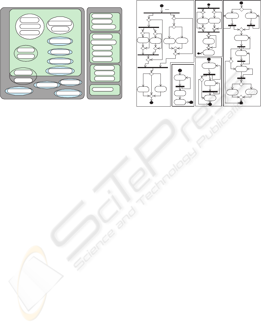
The application domain presented in this paper cor-
responds to one problem context that comprises four
legacy systems encapsulating 12 automated function-
alities, five non-automated functionalities and five
BPs that leverages the 17 functionalities in conduct-
ing the business logic. We focus on four legacy sys-
tems that have been customised around Australian
Stock Exchange (ASX) practices. Theses systems are
FATE, SMARTS, XSTREAM, and AUDIT Explorer.
Each of these systems supports a number of func-
tionalities accessible through APIs. In this paper, we
consider a few functionalities in each system that are
shown in figure 1. These functionalities have been re-
ported in (Yu et al., 2004; Dabous et al., 2003). We
also consider five BPs in this paper which are: ASX
trading data processing, visualisation of ASX trad-
ing data, reporting surveillance alerts, trading strategy
formalisation, and trading strategy execution. Figure
A FRAMEWORK FOR IDENTIFYING ARCHITECTURAL PATTERNS FOR E-BUSINESS APPLICATIONS
89
LG
F
all
F
au
Q2
RealTimeSim1
RealTime3
BAnalytic
Analytic2
Q4
TeSim1
TE3
Q3
TeSim1
FATE
RealTimeSim1
CurrDaySim1
XSTREAM
Realtime3
TE3
CurrDay3
AUDIT
VisualModel4
Q1
IntraDay2
CurrDay3
CurrDaySim1
SMARTS
CalibRun2
RealTimeAlerts2
IntraDay2
InterDay2
Analytic2
Q5
Q8
Q7
Q6
CalibRun2
RealTimeAlerts2
VisualModel4
InterDay2
Q12
Regulator
Q11
StrategyCnrl
Q10
OrderExeMgt
Q9
MktEventDetect
Figure 1: Selected application domain
IntraDay2
CurrDay3
Analytics2
VisualModel
BP2: Visualization
Today in Days
Mkt=asxMkt=asx
Old in Days
BP5: Trade Strategy exection
MktEventDetect
Event detected
StrategyCtrl
Ctrl msg
OrderExcMgt
RealTimeSim1 RealTime3
Subscriber event
triggered
Subscriber event
triggered
TE3
Order
palcement
Event=trade
else
Mkt= ASX-sim Mkt= ASX
Mkt= ASX-sim Mkt= ASX
TeSim1
CurrDay3
InterDay2
IntraDay2
Mkt =sim-ASX
Analytics2
BAnalytics
Metrics=smarts
Metrics=Beta
BP1: ASX Trading Data Processing
Mkt =rASX
Old in Days
Note: BP1 forms a sub-BP of BP2
CurrDaySim1
Today in Days
BP3: Surveillance
CalibRun2
RealTimeAlerts2
Regulator
Alert raised
BP4: Trade Strategy
formalisation
MktEventDetect
Event detected
StrategyCtrl
Ctrl msg
OrderExcMgt
Event=trade
else
Figure 2: Activity diagrams of the BPs
2 illustrates the workflow for each of these BPs as ac-
tivity diagrams. More details about the functionali-
ties, legacy systems, and the BPs that are used in this
application domain are discussed in (Dabous, 2005).
3 COMMON ARCHITECTURAL
DESCRIPTION
We propose a common architectural description with
the main motivation of facilitating a unified system-
atic architectural presentation. It describes each iden-
tified pattern in terms of a set of architectural compo-
nents Comp = {X
i
: 1 ≤ i ≤ |Comp|} which commu-
nicate with each other according to the BP descrip-
tion. A component X
i
∈ Comp is described accord-
ing to four essential features: denoted by the tuple
< tasks(X
i
), conT o(X
i
), invBy(X
i
), access(X
i
) >
where:
1. tasks(X
i
): is a function that identifies the set of
tasks that are encapsulated in the component X
i
.
These tasks can be one of three types. The first one
isthe implementation of a functionality f ∈ F
all
that is denoted by C(f ) and is used in three differ-
ent cases. The first is when f ∈ F
au
refers to an
existing legacy functionality within a legacy sys-
tem. The second is when f ∈ F
au
refers to rede-
veloping (i.e. reengineering) an existing function-
ality. The third is when f ∈ (F
all
− F
au
) which
is not implemented in any of the legacy systems.
The second one is he implementation of a wrapper
for a functionality f that is denoted by CW (f). It
is used when X
i
makes it possible to invoke the
functionality f from other components. The third
one is the implementing of the business logic of a
business process bp denoted by CBL(bp). We will
use the term ‘business process enactment’ to refer
to the implementation code of the business logic.
Note that these three tasks functions return the im-
plementation code resulted from applying the re-
spective task on its parameters. For example C(f )
returns the implementation code when applying the
‘create’ task on f (i.e. the code that implements f).
2. conT o(X
i
) ⊂ Comp: is a function that returns the
set of components that X
i
invokes while executing
its business logic.
3. invBy(X
i
) ⊂ Comp: is a function that returns the
set of components that invoke X
i
.
4. access(X
i
): a function that returns the access
method that is used by all X
j
∈ invBy(X
i
) to in-
voke X
i
. There are three main categories of access
methods that we consider. The first one is service-
oriented (SO) that presumes the existence of acces-
sible interfaces by means of a remote invocation us-
ing XML based protocols such as SOAP. The sec-
ond one is legacy-oriented that presumes the exis-
tence of APIs for local invocations whereas extra
code is required to make these APIs available for
remote invocations by means of binary protocols
that ranges from TCP/IP to RPC based protocols.
For this access method we used a function denoted
by api(l) : l ∈ LG that returns the API name of
the legacy system l that we also use as the access
method for the same legacy system. The third one
is ‘nil’ that is used when X
i
is not required for in-
vocation by any other X
j
∈ Comp. We denote the
set of all available access methods by the set AC
and therefore access(X
i
) ∈ AC ∀X
i
∈ Comp.
WEBIST 2005 - INTERNET COMPUTING
90
r1
r2
r3
d1
d4d3
d2
DS
For every c in P(DS)
Rules
Step 2 :generate architectural
construction algorithm by
combining all ds in c
validate
dispose
Step 4 :apply
pattern ranking/
selection method
Estimations
Ranked patterns
Preferences
Phase #1Phase #2
S
u
c
c
e
s
s
f
u
l
s
t
o
r
i
e
s
U
n
s
u
c
c
e
s
s
f
u
l
s
t
o
r
i
e
s
Pt
anti
Pt
cndt
Valid match
Not a valid match
Step 1 :instantiated
architectures for all
candidate patterns in Pt
cndt
Problem context
specification
Pt
frml
d1 d2 d3 d4
d4
d3
d4
d2
d3
d2d1
d4
d1
d3
d1
d2
d1
d3
d2
d1
d4
d2 d1
d4
d3
d4
d3d2
d1
d4d3
d2
Step 1 :generate P(DS)
Step 2 : apply
conseq. models
Step 3 : consult
stakeholders
Step 5 :Long-
term evolution
Figure 3: Framework for the patterns identification
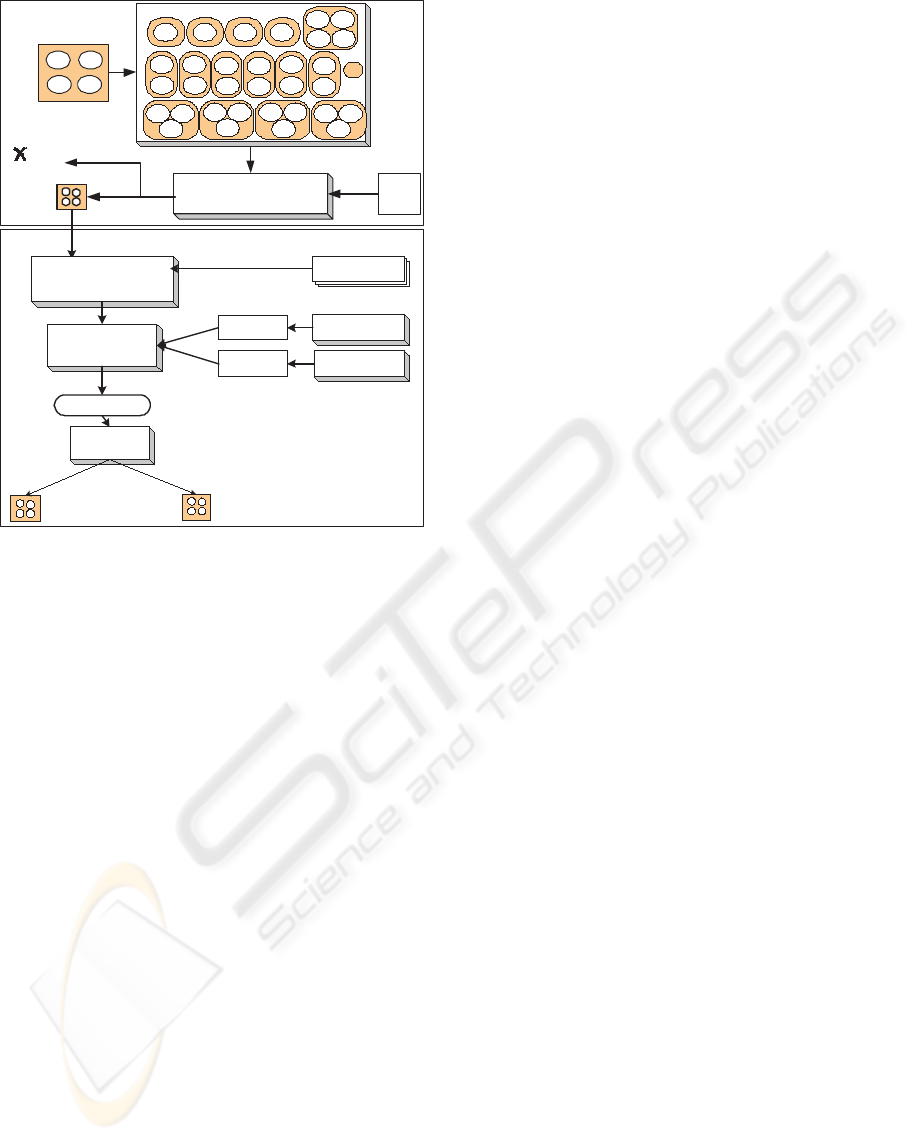
4 PATTERNS IDENTIFICATION
FRAMEWORK
This section presents an extensible systematic frame-
work for identifying domain-specific architectural
patterns for e-business applications. As illustrated in
figure 3,this framework comprises two phases: candi-
date patterns identification phase followed by the evo-
lution phase into formal patterns.
Phase #1: candidate patterns identification
This stage considers the identification of architec-
tural descriptions that correspond to candidate pat-
terns. This phase consists of two main steps:
1. Given a set of design strategies denoted by the DS
(see section 5) such that each strategy is formalised
using the common architectural description that is
discussed in section 3, generate the power set of all
subsets denoted by P(DS) that contains 2
|DS|
el-
ements. Each c ∈ P(DS) corresponds to a unique
possible combination of design strategies.
2. For each c ∈ P(DS) do the following: Firstly, let
arch
c
be the combined architectural construction
algorithms ∀d ∈ c. Secondly, having a set of com-
bining rules denoted by Rules (see section 5.2),
check arch
c
against all combining rules. If arch
c
is validated ∀r ∈ Rules, then arch
c
is added to
the set of candidate patterns denoted by P t
cndt
(i.e.
P t
cndt
= P t
cndt
∪ {arch
c
}), otherwise discard
arch
c
.
Phase #2: evolution into formal patterns
This stage considers the evolution opportunities for
the candidate patterns in P t
cndt
into either formal pat-
terns denoted by the set P t
frml
or anti-patterns de-
noted by the set P t
anti
. Theoretically, this evolution
process would result in P t
cndt
= P t
frml
∪ P t
anti
.
However, in reality, the evolutionary process for any
candidate pattern may take several years and depends
mostly on frequent use for that candidate pattern in
practice with different problems to generate either
successful solutions that push forward into formal
pattern or unsuccessful solutions that push forward
into anti-pattern. This phase consists of the five main
steps:
1. Instantiate the architectural description for each
identified candidate pattern in P t
cndt
on a given
application domain problem that is formalised with
accordance to the notations in section 2.1. Section
6 discusses the candidate patterns instantiations on
the application domain that is illustrated in section
2.2.
2. Apply the consequences estimation models, which
are discussed in (Dabous et al., 2005; Dabous,
2005), on the given application domain specifica-
tions so that estimation per model for each pattern
architecture is generated.
3. Investigate the stakeholders’ preferences on the re-
quired quality attributes that correspond to the pat-
terns’ consequences.
4. Apply a pattern selection algorithm based on steps
1, 2, and 3 using common MADM methods such
AHP which is discussed in (Al-Naeem et al.,
2005b). The outcome of such a selection method
is a rank for each pattern architecture in P t
cndt
.
5. The last step is to investigate possibilities of the
evolution of each candidate pattern. A candidate
pattern would gradually evolve into a formal pat-
tern in P t
frml
if it has been occupying one of
the higher ranks and successful stories have been
reported about its usage in practice. Otherwise,
such candidate pattern would gradually evolve into
an anti-pattern in Pt
anti
if it has been occupy-
ing lower ranks and/or unsuccessful stories have
been reported about its usage in practice. While
evolving, each candidate pattern documentation in
P t
cndt
would also be enriched with all experiences
with different problems context together with the
ranks, successful and unsuccessful stories.
Therefore, this framework is extensible because the
incorporation of one extra design strategy generates
A FRAMEWORK FOR IDENTIFYING ARCHITECTURAL PATTERNS FOR E-BUSINESS APPLICATIONS
91

extra |DS| combinations, and therefore possibly mo-
tivates extra candidate patterns wherever a valid com-
bination is generated. The framework is also system-
atic since all design strategies, candidate patterns, and
consequences models are defined around one com-
mon architectural description (the section 5), and
therefore a tool can be developed in order to navigate
through the steps of this framework. Due to space
limitations, this paper extends only to the first phase
of demonstrating the identification of a few candidate
patterns and step 1 in the second phase by applying
a realistic application from the domain of e-finance.
Indeed, related work to step 2 is reported in (Dabous
et al., 2005) and related work to steps 3 and 4 is re-
ported in (Al-Naeem et al., 2005b; Al-Naeem et al.,
2005a). Step 5 of phase 2, which requires long term
validation, is not yet addressed thoroughly in this re-
search.
5 DESIGN STRATEGIES AND
COMBINATION RULES
In this framework, we use the concept of ‘de-
sign strategy’ as a basic architectural construct
into the pattern identification process. Each de-
sign strategy is described using the common
architectural description. We use the notion
DS = {Reuse,Automate,Wrap,Migrate,MinCoordinate}
as the set of design strategies used in this paper. We
denote a set XLG to represent the architecture by
creating a component for every legacy system. This
set of components is presumed to exist. This set is
constructed using the following algorithm:
ConstructXLG (LG)
• For each l
x
∈ LG Do:
1. X
x
= createNew(); /* creates and initialises a new
component*/
2. access(X
x
) = api(l
x
);
3. tasks(X
x
) = {C(f
k
) : f
k
∈ l
x
};
4. XLG = XLG ∪ {X
x
} /* add X
x
to XLG */
Where createNew() function would create a compo-
nent X
x
of the same type as the components of Comp
and initialise its four features to nil (i.e. access()=
tasks()= conTo()= invBy()= nil). Whereas api(l
x
)
functions returns the access method that is supported
by the legacy system l
x
.
5.1 Design strategies
Reuse This design strategy considers the existing
legacy systems and the functionalities they embed
as existing assets that should be utilised immedi-
ately. Based on the proposed generic architecture,
this design strategy corresponds to creating |LG|
entries in Comp which have been already declared
as the content of the set XLG ⊂ Comp. The non-
automated functionalities (i.e. ∀f ∈ (F
all
− F
au
))
are not addressed in this design strategy. Its corre-
sponding algorithm is:
REUSE()
• For each X
i
∈ XLG
X
i
∈ XLG
X
i
∈ XLG:
– Comp = Comp ∪ {X
i
};
Automate This design strategy creates |F
all
− F
au
|
components each of which supports a new func-
tionality that does not exist in any of existing legacy
systems. This strategy implements a unified ac-
cess type for these new functionalities (i.e. ∀f ∈
(F
all
− F
au
)). This is accomplished using the fol-
lowing algorithm:
AUTOMATE(ac) /*ac is the access method used*/
• For each f
k
∈ (F
all
− F
au
)
f
k
∈ (F
all
− F
au
)
f
k
∈ (F
all
− F
au
):
1. X
x
= createNew ();
2. access(X
x
) = ac;
3. tasks(X
x
) = {C(f
k
)};
4. Comp = Comp ∪ {X
x
};
Wrap This design strategy considers a unified access
method for all functionalities identified in the set
of legacy systems (i.e. ∀f
i
∈ F
au
). It creates a
total of |F
au
| components in Comp each of which
corresponds to a wrapper component (i.e. for every
functionality that resides in a legacy system) . This
is accomplished using the following algorithm:
WRAP (ac)
• For each X
i
∈ XLG such that X
i
∈ Comp
X
i
∈ XLG such that X
i
∈ Comp
X
i
∈ XLG such that X
i
∈ Comp do:
– For each C(f
k
) ∈ tasks(X
i
):
1. X
x
= createNew();
2. access(X
x
) = ac;
3. tasks(X
x
) = {CW (f
k
)};
4. invBy(X
i
) = X
x
5. conT o(X
x
) = X
i
6. Comp = Comp ∪ {X
x
}
Migrate This design strategy ignores existing legacy
systems and therefore redevelops the functionali-
ties ∀f ∈ F
all
with a unified access method. This
strategy groups each set of equivalent functionali-
ties q ∈ Q in one component. Therefore, it cre-
ates a total of |Q| new components in Comp where
each new component corresponds to one q ∈ Q
and contains a task C(f
k
) for each f
k
∈ q. This is
accomplished using the following algorithm:
MIGRATE(ac) /*ac is the access method used*/
• For each q
i
∈ Q
q
i
∈ Q
q
i
∈ Q:
1. X
x
= createNew ();
2. access(X
x
) =ac;
3. tasks(X
x
) = {C(f
k
) : f
k
∈ q
i
};
4. Comp = Comp ∪ {X
x
}
WEBIST 2005 - INTERNET COMPUTING
92

MinCoordinate Minimum Coordinate (MinCoordi-
nate) design strategy relates to the implementation
of every bp
j
∈ BP enactment as an autonomous
component that depends directly on the activities
denoted by activities(bp). This design strategy
mandates that any bp ∈ BP should implement
its own private copy of any required functional-
ity that is not supported in any other component
in Comp. Meaning that an f ∈ F
all
such that
C(f) /∈ tasks(X
i
)∀X
i
∈ Comp should imple-
ment an instance of f that is accessed only by X
i
and therefore tasks(X
i
) = tasks(X
i
) ∪ {C(f)}.
This design strategy is accomplished using the fol-
lowing algorithm:
MINCOORDINATE()
1. Let BpComp =φ /* An empty set of same type as
Comp*/
2. For each bp
j
∈ BP
bp
j
∈ BP
bp
j
∈ BP :
(a) X
x
= createNew ();
(b) access(X
c
) = φ;
(c) tasks(X
x
) = {CBL(bp
j
)};
(d) For each f
k
∈ activities(bp
i
) DO:
• IF (∃X
i
: C(f
k
) ∈ tasks(X
i
))
– conT o(X
x
) = conT o(X
x
) ∪ {X
i
};
– invBy(X
i
) = invBy(X
i
) ∪ {X
x
};
• ELSE tasks(X
x
) = tasks(X
x
) ∪ {C(f
k
)};
(e) BpComp = BpComp ∪ {X
x
};
3. Comp = Comp ∪ BpComp;
5.2 Design strategies combination
rules
The design strategies are combined by linearly apply-
ing their corresponding construction algorithms. The
order in which the participating design strategies are
combined with the aim of generating a ‘valid’ combi-
nation is significant. This order is based on associated
rank for each strategy. The first rank is for ‘Reuse and
‘Migrate’, the second is for ‘Automate’ and ‘Wrap’,
the third is for ‘MinCoordinate’ design strategy. The
naming convention for the patterns that we consider
shows the participating design strategies in the cor-
rect combining order.
We have investigated the major combining rules
that are applied to any possible design strategies com-
bination and therefore considering this combination
as either valid or invalid. The main idea for such rules
is to make sure that the combined design strategies
algorithms can form a neat architecture when applied
on any problem context specification. A neat architec-
ture would guarantee that Comp architecture facili-
tates the connectivity from any business process to all
of its required functionalities without redundancies.
The following rules are the major ones that should ap-
ply in order to consider a valid design strategies com-
bination and therefore a candidate pattern:
1. Existence of tasks that implements all BPs logic:
For every bp ∈ BP, ∃X
i
: CBL(bp) ∈ tasks(X
i
).
2. Existence of tasks that implement all functionalities
in F
all
:
For every f ∈ F
all
, ∃X
i
: C(f) ∈ tasks(X
i
).
3. A functionality can have one and only one wrapper
component:
If CW (f) ∈ tasks(X
i
) and CW (f ) ∈ tasks(X
z
)
such that access(X
i
) = access(X
z
) then X
i
= X
z
.
4. Non-redundancy of a BP logic implementation task:
If CBL(bp) ∈ tasks(X
i
) and CBL(bp) ∈ tasks(X
z
)
then X
i
= X
z
.
5. Redundancy of a functionality implementation can be
found locally in any BP that requires it if that func-
tionalities is not created publicly elsewhere:
If C(f ) ∈ tasks(X
i
) and C(f ) ∈ tasks(X
z
) : X
i
6=
X
z
then CBL(bp
a
) ∈ X
i
and CBL(bp
b
) ∈ X
z
: a 6=
b.
Otherwise, the generated combination will be ‘in-
valid’ and therefore it is not considered as a candidate
pattern. For instance, such invalid combinations may
generate the following cases:
I The existence of redundancy across the tasks of the
matched design strategies (e.g. ∃C(f ) : C(f) ∈
tasks(X
i
) and ∈ tasks(X
j
) where X
i
and X
j
are in different design strategies).
II The existence of missing tasks that one of the par-
ticipant design strategies should contain (e.g. For
any f ∈ F
all
∄X
i
: C(f ) ∈ tasks(X
i
)).
By applying these rules, we obtained seven valid com-
binations each of which constitutes candidate pat-
tern. The first five patterns are more likely to evolve
into formal patterns because they are initially iden-
tified based on practical experience and reported in
(Dabous, 2005) whereas the other two are expected
to evolve into anti- patterns because they promote the
isolation of standalone BP implementation that is ob-
solete and does not correspond to current practices.
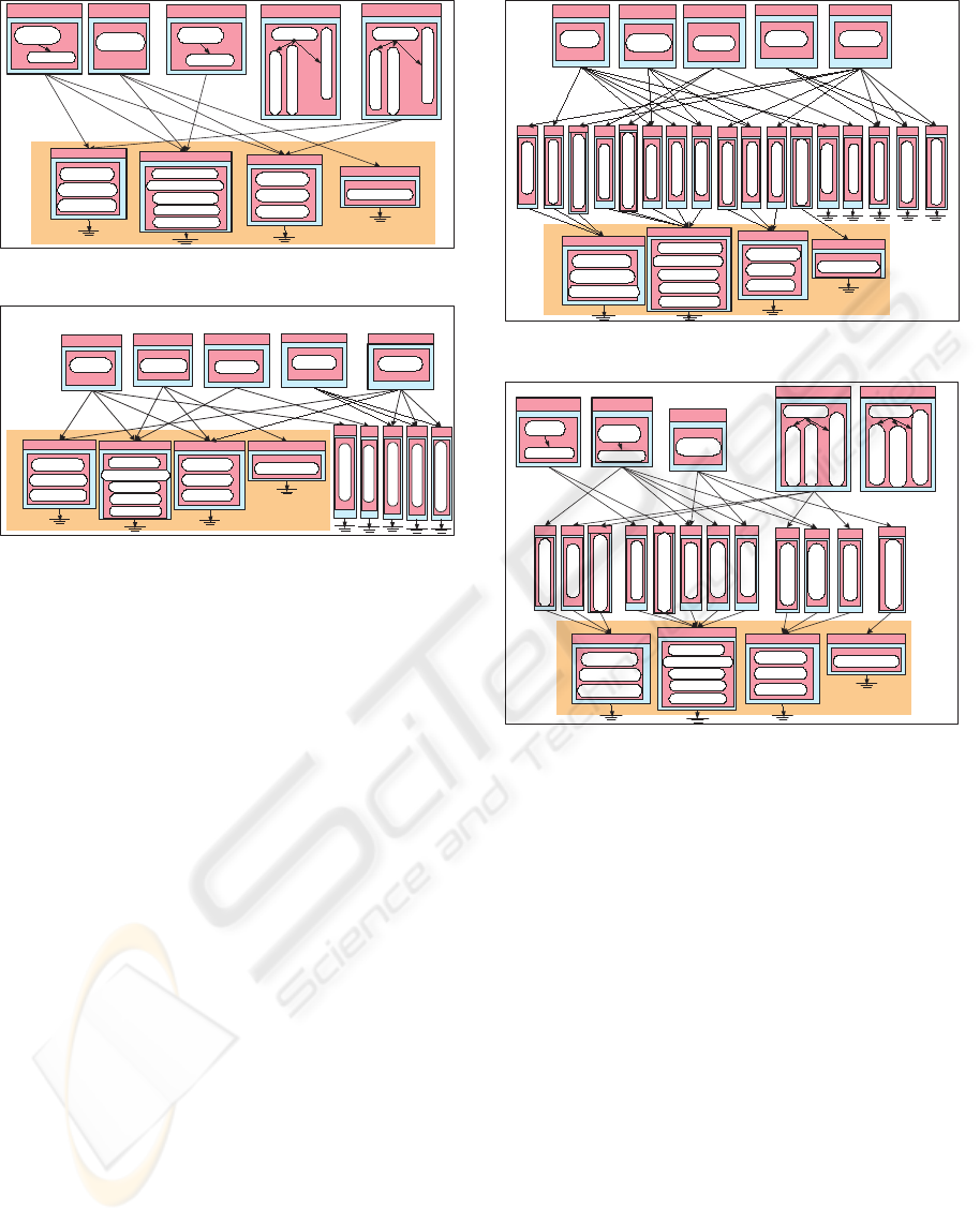
6 CANDIDATE PATTERNS
Now we briefly discuss the architectural descrip-
tion of the five candidate patterns. Details of their
forces and consequences are discussed thoroughly in
(Dabous, 2005). We also show the architecture gen-
erated when instantiating each candidate pattern on
the selected application domain (i.e. the contents of
the set Comp). Figures 4-8 illustrate visually the con-
tents of the set Comp for these five architectures. In
these figures, each box (i.e. component) corresponds
to an X
i
∈ Comp showing its tasks as ovals and ac-
cess method on the top of the box whereas each arrow
(i.e. link) from X
a
to X
b
means that X
b
∈ conT o(X
a
)
and X
a
∈ invBy(X
b
). The patterns instantiations of
A FRAMEWORK FOR IDENTIFYING ARCHITECTURAL PATTERNS FOR E-BUSINESS APPLICATIONS
93
XLG
Access() = nil
CBL(BP5)
C(MktEventDetect)
C(OrderExeMgt)
C(StrategyCnrl)
Access() = nil
CBL(BP4)
C(MktEventDetect)
C(OrderExeMgt)
C(StrategyCnrl)
Access() = nil
CBL(BP3)
C(Regulator )
Access() =nil
CBL(BP2)
Access() = nil
CBL(BP1)
C(BAnalytics )
Access() = API1
C(TeSim1)
C(RealTimesim1)
C(CurrDaySim1)
Access() = API3
C(RealTime3)
C(CurrDay3)
C(TE3)
Access() = API4
C(VisualModel4)
Access() = API2
C(CalibRun2)
C(RealTimeAlerts2)
C(IntraDay2)
C(InterDay2)
C(Analytic2)
Figure 4: Pt1 applied on the application domain
XLG
SO
C(MktEventDetect)
SO
C(OrderExeMgt)
SO
C(StrategyCnrl)
SO
C(Regulator)
SO
C(BAnalytics)
Access() = API3
C(RealTime3)
C(CurrDay3)
C(TE3)
Access() = API4
C(VisualModel4)
Access() = API1
C(TeSim1)
C(RealTimesim1)
C(CurrDaySim1)
Access() = API2
C(CalibRun2)
C(RealTimeAlerts2)
C(IntraDay2)
C(InterDay2)
C(Analytic2)
Access() = nil
CBL(BP1)
Access() =nil
CBL(BP2)
Access() = nil
CBL(BP3)
Access() = nil
CBL(BP4)
Access() = nil
CBL(BP5)
Figure 5: Pt2 applied on the application domain
the application domain correspond to the second step
of the second phase in the proposed framework. We
provide our naming convention for each pattern as fol-
lows:
Reuse+MinCoordinate (Pt1) This pattern considers
generating invocations to the required functional-
ities across legacy system by direct invocations
through the APIs of these systems. On the other
hand, each BP implements its local program code
for each of its activities that have no corresponding
functionality in any of the legacy systems. Figure
4 shows the architecture of Pt1 instantiation on the
selected application domain.
Reuse+Automate+MinCoordinate (Pt2) This pat-
tern considers generating an invocation to the re-
quired functionalities across legacy system by di-
rect invocation through the APIs of these sys-
tems. It also considers implementing all activities
of BPs that have no correspondence in any of the
legacy systems as global e-services with advertised
service-based interface. Figure 5 shows the archi-
tecture of Pt2 instantiation on the selected applica-
tion domain.
Reuse+Wrap+Automate+MinCoordinate (Pt3)
This pattern considers providing a unified service-
based interface to every particular functionality
across legacy systems. This provision is achieved
by developing service-based Wraps. It also con-
siders implementing all activities of BPs that have
no correspondence in any of the legacy systems
XLG
Access() = nil
CBL(BP5)
Access() = nil
CBL(BP3)
Access() =nil
CBL(BP2)
Access() = nil
CBL(BP1)
SO
C(MktEventDetect)
SO
C(OrderExeMgt)
SO
C(StrategyCnrl)
SO
C(Regulator)
SO
C(BAnalytics)
SO
CW(RealTimeSim1)
SO
CW(CurrDaySim1)
SO
CW(TeSim1)
SO
CW(VisualModel4)
SO
CW(TE3)
SO
CW(CurrDay3)
SO
CW(RealTime3)
SO
CW(Analytic2)
SO
CW(InterDay2)
SO
CW(IntraDay2)
SO
CW(RealTimeAlerts2)
SO
CW(Calibrun2)
Access() = API1
C(TeSim1)
C(RealTimeSim1)
C(CurrDaySim1)
Access() = API3
C(RealTime3)
C(CurrDay3)
C(TE3)
Access() = API4
C(VisualModel4)
Access() = API2
C(CalibRun2)
C(RealTimeAlerts2)
C(IntraDay2)
C(InterDay2)
C(Analytic2)
Access() = SO
CBL(BP4)
Figure 6: Pt3 applied on the application domain
XLG
SO
CW(RealTimeSim1)
SO
CW(CurrDaySim1)
SO
CW(TeSim1)
SO
CW(VisualModel4)
SO
CW(TE3)
SO
CW(CurrDay3)
SO
CW(RealTime3)
SO
CW(Analytic2)
SO
CW(InterDay2)
SO
CW(IntraDay2)
SO
CW(RealTimeAlerts2)
SO
CW(Calibrun2)
Access() = API1
C(TeSim1)
C(RealTimeSim1)
C(CurrDaySim1)
Access() = API3
C(RealTime3)
C(CurrDay3)
C(TE3)
Access() = API4
C(VisualModel4)
Access() = nil
CBL(BP1)
C(BAnalytics )
Access() =nil
CBL(BP2)
Access() = nil
CBL(BP3)
C(Regulator )
Access() = nil
CBL(BP4)
C(MktEventDetect)
C(OrderExeMgt)
C(StrategyCnrl)
Access() = nil
CBL(BP5)
C(MktEventDetect)
C(OrderExeMgt)
C(StrategyCnr)l
Access() = API2
C(CalibRun2)
C(RealTimeAlerts2)
C(IntraDay2)
C(InterDay2)
C(Analytic2)
Figure 7: Pt4 applied on the application domain
as global e- services with advertised service-based
interface. Figure 6 shows the architecture of Pt3
instantiation on the selected application domain.
Reuse+Wrap+MinCoordinate (Pt4) This pattern
considers providing a unified service-based inter-
face to every particular required function- ality
across legacy systems. This provision is achieved
by developing service-based Wraps. On the other
hand, each BP implements its local program code
for each of its activities that have no corresponding
functionality in any of the legacy systems. Figure
7 shows the architecture of Pt4 instantiation on the
selected application domain.
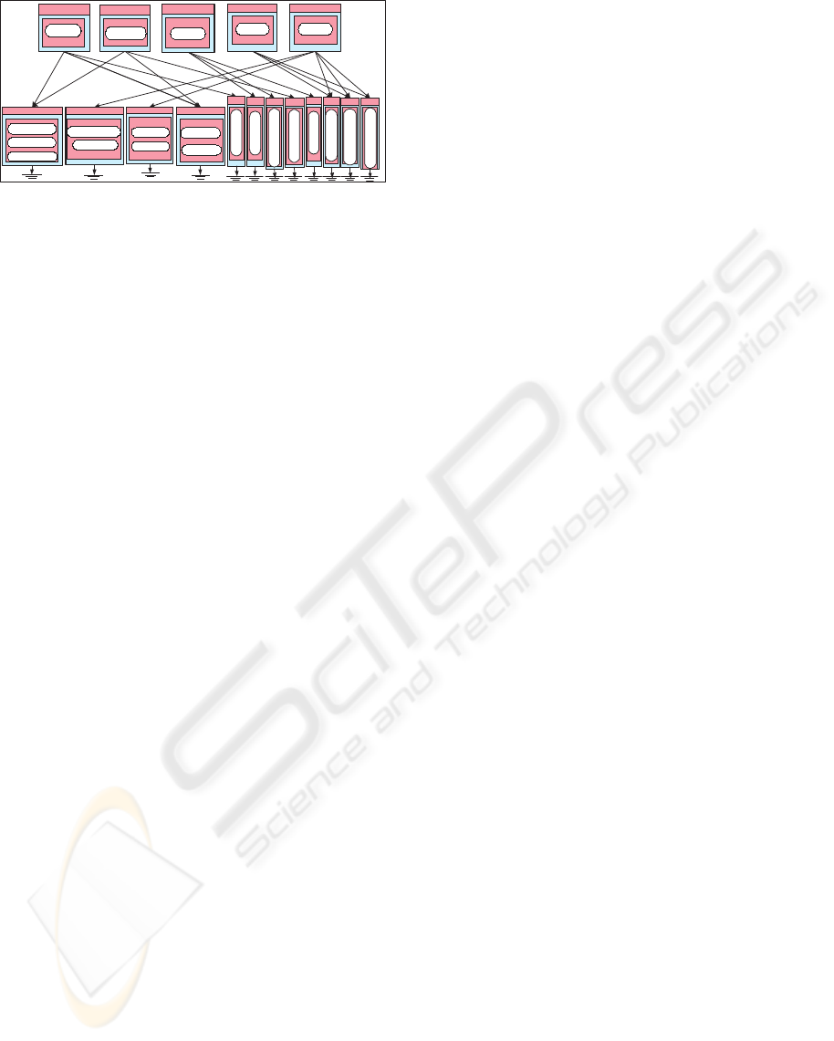
Migrate+MinCoordinate (Pt5) This pattern con-
siders the disposal or abandoning existing legacy
systems. Therefore, starting from scratch, this pat-
tern migrates the implementation of required func-
tionalities through a re-engineering/automation
process into global e-services with advertised
service-based interface. In this process, each
group of equivalent functionalities are reengineered
within a single program that supports one interface.
WEBIST 2005 - INTERNET COMPUTING
94
SO
C(InterDay2)
SO
C(VisualModel4)
SO
C(RealTimeAlerts2)
SO
C(CalbRun2)
SO
C(MktEventDetect)
SO
C(OrderExeMgm)
SO
C(StrategyCnrl)
SO
C(Regulator)
Access= SO
C(Banalytic)
C(Analytic2)
Access= SO
C(TeSim1)
C(TE3)
Access= SO
C(RealTimeSim1)
C(RealTime3)
Access= SO
C(CurrDaySim1)
C(IntraDay2)
C(CurrDay3)
Access() = nil
CBL(BP1)
Access() =nil
CBL(BP2)
Access() = nil
CBL(BP3)
Access() = nil
CBL(BP4)
Access() = nil
CBL(BP5)
Figure 8: Pt5 applied on the application domain
Figure 8 shows the architecture of Pt5 instantiation
on the selected application domain.
MinCoordinate (Pt6) and Automate+MinCo. (Pt7)
are more likely to evolve into anti-patterns because
they promote the isolation and standalone BP
implementation that is obsolete and does not
correspond to current practices.
7 CONCLUSION
In this paper, we presented and discussed the basic
components of a systematic extensible framework for
identifying patterns for the architectural design of a
category of applications in the e-business domain.
This work is motivated by three factors. The first one
is the availability of five architectural patterns that are
identified and formalised in (Dabous, 2005) based on
practical experience in developing e-business appli-
cations that utilise legacy functionality in the domain
of e-finance. The second one is the quality models
reported in (Dabous, 2005; Dabous et al., 2005) that
estimate the patterns consequences for a given appli-
cation domain specification. The third one is the ar-
chitectural patterns selection method based on AHP
that is reported in (Al-Naeem et al., 2005b; Al-Naeem
et al., 2005a).
The proposed framework is systematic and extensi-
ble. It is systematic since the formalisation of the de-
sign strategies, the candidate patterns and the quality
models uses the same common architectural descrip-
tion. It is also extensible since the identification of
each extra design strategy would duplicate the number
of strategies combinations and therefore possibly trig-
gers extra candidate patterns. In (Dabous, 2005), we
illustrated the impact of introducing additional two
strategies on identifying more candidate patterns.
Current work focuses on providing tool support for
automatic generation of the candidate patterns archi-
tectures for a given application domain specification
and for ranking the architectures generated by instan-
tiating these patterns with accordance to their appro-
priateness based on both the estimations provided by
the quality models and the preferences for such qual-
ity provided by stakeholders.
REFERENCES
Al-Naeem, T., Dabous, F. T., Rabhi, F. A., and Beatallah,
B. (2005a). Formulating the architectural design of
enterprise applications as a search problem. In Aus-
tralian Software Engineering Conference (ASWEC
2005), Australia. Computer society Press.
Al-Naeem, T., Dabous, F. T., Rabhi, F. A., and Benatal-
lah, B. (2005b). Quantitative evaluation of enterprise
integration patterns. In 7th Int. Conf. on Enterprise
Information Systems (ICEIS05), Miami, USA.
Anderson, D., Sweeny, D., and Williams, T. (2002). An In-
troduction to management Science: Quantitative Ap-
proaches to Decision Amking. South-Western Educa-
tional Publishing.
Dabous, F. T. (2005). Pattern-Based Approach for the Ar-
chitectural Design of e-Business Applications. Phd
thesis, School of Information Systems, Technology
and Management, The University of New South
Wales, Australia. (to be submitted in Apr 2005).
Dabous, F. T., Rabhi, F. A., and Yu, H. (2003). Perfor-
mance issues in integrating a capital market surveil-
lance system. In Proceedings of the 4th International
Conference on Web Information Systems engineering
(WISE03), Rome, Italy.
Dabous, F. T., Rabhi, F. A., Yu, H., and Al-Naeem, T.
(2005). Estimating patterns consequences for the
architectural design of e-business applications. In
7th Int. Conf. on Enterprise Information Systems
(ICEIS05), Miami, USA.
Harris, L. (2003). Trading and Exchanges: Market Mi-
crostructure for Practitioners. Oxford University
Press.
Rabhi, F. A., Dabous, F. T., Chu, R. Y., and Tan, G. E.
(2003). SMARTS benchmarking, prototyping & per-
formance prediction. Technical Report CRCPA5005,
Capital Market Cooperative Research Center (CM-
CRC).
Yu, H., Rabhi, F. A., and Dabous, F. T. (2004). An ex-
change service for financial markets. In 6th Interna-
tional Conference on Enterprise Information Systems
(ICEIS04), Porto, Portugal.
A FRAMEWORK FOR IDENTIFYING ARCHITECTURAL PATTERNS FOR E-BUSINESS APPLICATIONS
95
