
A NEW VISION OF CONTROL FOR A SMART HOME
Pavlo Krasovsky, Jochen Seitz
Institute of Information Technique,
Department of Communication Networks,
Technische Universität Ilmenau,
D-98684,Ilmenau, Germany
Keywords: Wireless applications, ubiquitous computing, XML, and data management
Abstract: Intelligent systems that provide integrated control for many functions, such as lighting, safeguard, air-
conditioner, heating, housekeeping equipment and maintenance of electronics, are close at hand for the mass
market. Main factors for the increase in needs of intelligent systems are: reduction of price, reputation of
products, and technical improvements. There are many corresponding systems, control equipment and ser-
vices at the market now. The main goal is the complete integration of all functions. It demands a high level
of interoperability between equipment and subsystems. The most important and advanced stage of devel-
opment is the remote control via internet or telephone. In the context of our project we developed a new
concept of interaction between server-side hardware and end-user software. The main purpose is to develop
a control system for the smart home in terms of communication and automation modules, first of all in a
wireless range. A communication interface should allow changing properties of end-user software without
recompilation. All necessary changes should happen in the server-side software with the help of configura-
tion files. One can use any text editor to change these files. Client software has to have full control of the
automation equipment at real time.
1 INTRODUCTION
Home networking has already emerged in specific
applications such as PC-to-PC communication and
home entertainment systems, but its ability to really
change people’s lives is still being retarded by com-
plex installation procedures, the lack of interopera-
bility between different manufacturers’ equipment
and the absence of compelling user services (Amigo,
2004).
There are many companies at the market now that
are occupied with the intelligent technique. They
offer different complex solutions of automation of
buildings, plants etc. Mainly, it is gathering informa-
tion from devices to the main terminal and remotely
controlling these devices, sometimes simply for
monitoring important equipment. It is very difficult
to retrieve information about these systems because
they implement rather new technologies and the
companies do not want to share their knowledge and
know-how. Therefore, there are still no standards at
the market now for building similar systems. That is
why these systems are yet not so popular.
In the context of the project LISTIG (LAN–
integrated control system for intelligent building
technique) two companies in Germany, DE-
SOTRON (http://www.desotron.de/) from Söm-
merda and Hörmann Funkwerke Kölleda
(http://www.hfwk.de/), cooperate to create a market-
able product in this area with an open architecture of
communication and very simple reconfigurable
structure (DESOTRON, 2003). Therefore, they inte-
grated teams of the University of Applied Sciences,
Jena and of the Technische
Universität Ilmenau in the
specification process.
The key objective of the LISTIG project is to
make technology not only work from a technical
point of view, but to make it work in such a way that
it motivates all people to use networked home sys-
tems with great ease and pleasure. This is also the
reason to spend much effort in developing attractive
user services and application prototypes that will
result in end-user benefits of a networked home sys-
tem. The use of a LISTIG networked home system
must relieve the boredom of household tasks, cause
pleasant experiences and simplify information re-
trieval.
117
Krasovsky P. and Seitz J. (2005).
A NEW VISION OF CONTROL FOR A SMART HOME.
In Proceedings of the First International Conference on Web Information Systems and Technologies, pages 117-124
DOI: 10.5220/0001231201170124
Copyright
c
SciTePress

The main scientific and technical idea is a useful
combination of communication and automation
technique for controlling integrated systems for
smart buildings. These two technologies have to
bring the cheapest solution with the help of useable
embedded microcomputers (LISTIG – basis device)
that has very flexible possibilities for modification
through replaceable modules and chip cards.
2 STATE OF THE TECHNIQUE
The automation technique plays an important role in
our life (House, 2004). Only few professional activi-
ties exist that do not confront with the automation
nowadays. There are many heating and lighting
automatons in “house” areas that play a vanguard
role. The pervasion of automatons in the manufac-
turing industry is quite common today. The produc-
tion lines with robots are in all factory buildings and
implement products, for example automobiles. The
computer technique has already penetrated deeply
into our offices and houses and the automation tech-
nique is used step by step first of all in forms of
alarm and security equipment. Many buildings have
already been equipped with heating, ventilation,
lighting etc. These automation systems primarily
have to save electric power and furthermore manage
and control. The improvement of flexibility and in-
crease of work and life comfort play an important
role. The automation systems with peripheral
“autonomous” responsibility and intelligent strategic
observation and accompaniment are available in
praxis as exemplary models.
The technical solutions for smart houses and
buildings are already available or in development
even if they have a high price and are not optimized.
Here are some examples. The Medical Automation
Research Center (MARC) at the University of Vir-
ginia has developed technological solutions for in-
home monitoring of residents in order to provide
quality of life indicators (MARC, 2004). The in-
home monitoring system is composed of a suite of
low-cost, non-invasive sensors (strictly no cameras
or microphones), and a data logging and communi-
cations module, in addition to an integrated data
management system. The company Honeywell from
Austria proposes their system solution for building
automation and security with controlling all techni-
cal equipment and open managing of building on
demand (Honeywell, 2003). A very interesting pro-
ject called Amigo started at the end of 2004. Fifteen
of Europe’s leading companies and research estab-
lishments in mobile and home networking, software
development, consumer electronics and domestic
appliances have joined together in Amigo – an inte-
grated project that will realize the full potential of
home networking to improve people’s lives. The
project will develop open, standardized, interoper-
able middleware and attractive user services, thus
improving end-user usability and attractiveness
(Amigo, 2004). The main advantage of intellectual
system of control Berrimor is controlling and moni-
toring without the human influence (Berrimor,
2004).
All these projects have their advantages, but there
are still some disadvantages. A comparison of these
projects and the LISTIG project should be presented
at the conference.
The project LISTIG wants to develop an inte-
grated system of controlling, managing and monitor-
ing what doesn’t exist at market now. It is an attempt
to bring to the market a new concept of vision the “i-
Living” that means: intelligent, informative, individ-
ual, integrated and innovative, which relies on using
mainly wireless technologies and which will lead to
lower prices for buying and installing this system.
3 ARCHITECTURE OF LISTIG
The LISTIG basis device is a specific microcom-
puter developed by DESOTRON (see figure 1).
It has following basic specifications: 486 Atlas
CPU with mathematical coprocessor, 128 MB
SDRAM, 8 MB Flash RAM, without hard disk but
with enhanced network opportunities such as
Ethernet, WLAN, BLUETOOTH. The microcom-
puter works under control of the operating system
UNIX (Debian).
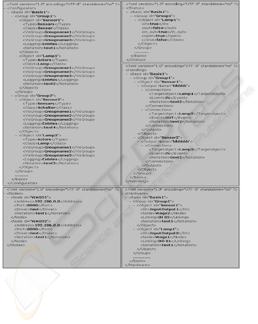
The basic architecture is represented in Figure 2
(Müller, 2004). The mode of functioning is as fol-
lows: the terminal equipment such as PC, PDA or
Handy sends a query to the visualization server that
processes the received information and sends back
the response to the terminal or forwards the query to
the automation server. The automation server, ac-
cording to the received information, sends a signal to
the well-defined equipment such as sensing devices,
lamps, heating, sirens, dimmers, etc., and receives
the acknowledgement signal; which it then forwards
via the visualization server to the terminal.
From the point of view of the software, heating,
sirens, dimmers and other equipment are objects that
belong to the groups that are situated on one or sev-
eral basis LISTIG devices. These objects interact
with each other through XML-messages.
WEBIST 2005 - INTERNET COMPUTING
118
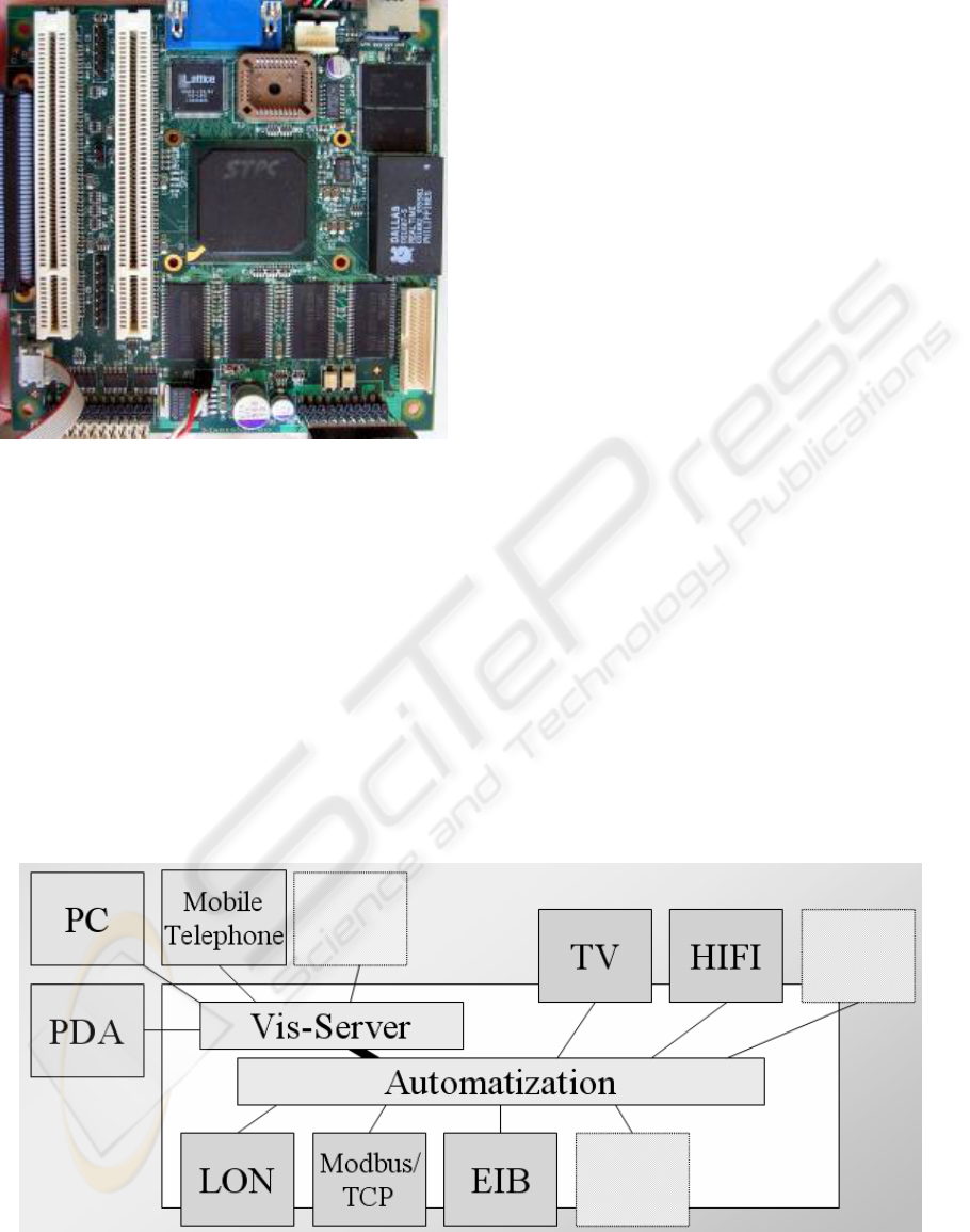
Figure 1: The LISTIG basis device
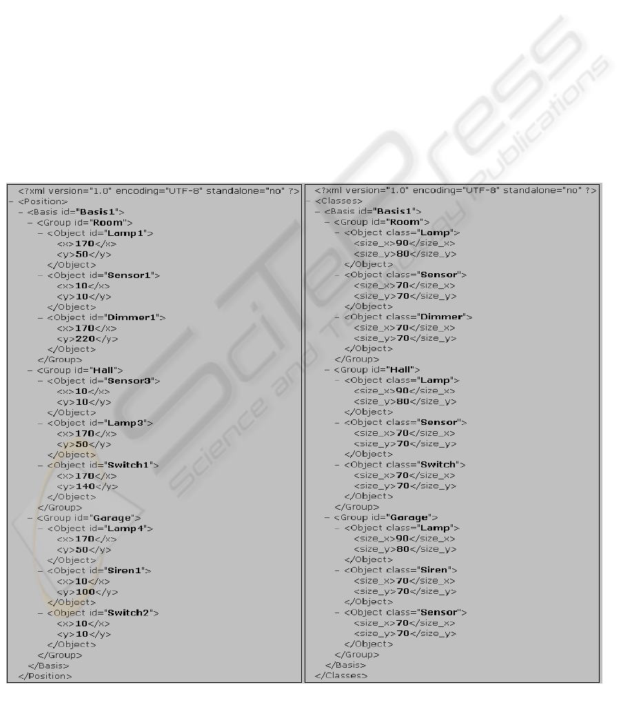
4 SOFTWARE AND HARDWARE
The software of the LISTIG project has a complex,
branchy structure. It consists of the client-side soft-
ware for the end-user terminals and the server-side
software comprising three servers. The hardware is
an aggregate of equipment that is physically con-
trolled by microcontrollers WAGO. The controlling
with the software is realized via six configuration
files, see figures 3 and 4. These files have an XML
format and can be modified by any text editor.
The “Nodes.xml” file describes an access to
the various input-output (I/O) nodes of the network
(not for visualization).
The “Hardware.xml” file describes connec-
tions of objects with physical I/O-points or with
functions of physical devices (not for visualization).
The “Handling.xml” file describes the linking
of objects among themselves.
The “Configurator.xml” file describes what
objects are procreated, their classes, type, and as-
signment to the group, and an arbitrary number of
visualization groups. The name of the group and the
basis device always belong to the object name. So
we can always identify the object even if there is
more than one basis device in our system.
The “Classes.xml” file describes what ob-
jects can be shown at the terminal and the size of
this object in pixels. For example, an object belongs
to the current visualization group but you do not
want to see it on the screen or for some visualization
group the end-user would like to change the geomet-
ric representation of object.
The “Position.xml” file describes the loca-
tion of the objects on the screen. Location is deter-
mined with two coordinates and it always refers to
the left-upper corner of virtual rectangle.
The client software has been written for two
classes of computers, PC’s and pocket organizers.
The software for Pocket PC’s has been written in
C# with the help of Microsoft Visual Studio .NET.
For PC’s there are two clients in C# and Java from
Sun. The possibilities of PC’s and Pocket PC’s are
strongly different that is why the main difference in
the software is their ability to monitor and control
the whole system and the one visualization group
correspondingly. The application consists of many
specific classes for every type of equipment.
Figure 2: The basic LISTIG architecture
A NEW VISION OF CONTROL FOR A SMART HOME
119
Every class has its own quantity of parameters that
corresponds to the real physical device. In another
thread of this application a TCP server is started on a
certain port that listens to the messages from the
visualization server. After successful identification
and authentication the application reads the configu-
ration information from the visualization server and
on the basis of this information receives data about
lamps, sensing devices, etc., that are available in this
system and dynamically creates the necessary
amount of objects of every class of equipment. It
means that it is possible to create one, two or n logi-
cal end-devices from one class.
Theoretically, the quantity of objects is unlimited,
but practically it is limited with the RAM of the end-
user terminals.
On the PDA; we chose several hierarchical views.
At first, one can see all virtual visualization groups,
classes and names of objects that one can monitor
and control. After selecting the group you would like
to observe, you receive the current state of all ob-
jects in this group, then you can see or change the
state of any object in this group. The feature of the
Figure 3: Configuration Files (I)
WEBIST 2005 - INTERNET COMPUTING
120
software is that the system is completely dynamic
and flexible. It means that with the help of the file
“Configurator.xml” you can create as many
virtual groups as you need and logically configure
all equipment at your wish. For example, it is very
comfortable to have the ability to see and control all
heating devices or lamps on one screen. Thereby,
one can receive quickly and easily necessary infor-
mation.
The data transfer from the client to the visualiza-
tion server is implemented on UDP sockets. There is
no need to do TCP communication for several rea-
sons. At first, TCP communication works a little bit
slower than UDP. There is no sense to permanently
have an open communication between client and
visualization server because of the poor abilities of
basis hardware. The loss of a UDP packet is also not
a critical error because there are no obligatory ac-
knowledgements in the system! Whenever you
change something in the system you can immedi-
ately see your changes. If you see nothing after a
few seconds it means that the packet was lost and
you have to send it again.
The server-side software is a distributed applica-
tion consisting of three servers: a logging server, an
automation server called communicator and the
aforementioned visualization server. Normally all
these servers should have been located on one
LISTIG device, but it is not obligatory.
The logging server keeps logs of the events of all
information about the system, namely:
- messages between terminals and visualiza-
tion server, between visualization server
and communicator;
- successful and failed connection attempts;
- IP-addresses of all terminals that have ever
been connected;
- date and time of received and sent packets;
- statistics of all events on demand.
The Communicator is a server, written in C++. It
consists of a collection of classes that have a low-
level interface to the equipment. Every class is a
virtual unit that controls the hardware. It means that
this server receives an XML string from the visuali-
Figure 4: Configuration Files (II)
A NEW VISION OF CONTROL FOR A SMART HOME
121

zation server, processes this message and controls
the equipment (for example switching on/off the
lamp) without physical cooperation. On start, the
server reads the configuration information from
three configuration files and accordingly links logi-
cally all sensors and actuators. It can be very useful,
for example that you can link one sensing device to
all lamps in your house. The Communicator com-
municates with the visualization server with the help
of TCP sockets. It means that the application listens
for all packets on a certain port. Access to this port
is permitted only for the packets inside of the opera-
tion system and blocked from the end-user terminals
or somewhere else.
The visualization server is the heart of this inte-
grated system, written in C/C++. It links two parts of
the system – end-user terminals and automation.
This server is a multithreaded application that is
responsible for processing, receiving and sending
packets and possesses some smart functions. On one
hand, after starting the server, it listens to the given
UDP port and waits for the messages from end-user
terminals. Upon receiving a message from the end-
user terminals, the server analyses the received in-
formation. It sends a response or relays this informa-
tion to the Communicator. In order to respond, the
server establishes a TCP connection with the end-
user terminal. The type of responses can be as fol-
lows:
- access denied or granted;
- login or password is not valid;
- MAC-address is not valid;
- various replies for the configuration re-
quests: configuration, position and location
of objects.
The authentication of the end-user is linked with the
account of the user in the operating system UNIX. If
none of the messages corresponds to the types
above, the server sends this message to the Commu-
nicator for the next processing.
When starting the visualization server, the option
of checking the MAC-address of the end-user termi-
nals could be selected. This means that the terminals
have to be in a LAN (Local Area Network) and to be
in the same subnetwork that has the LISTIG basis
device.
On the other hand, on the start of the server a
TCP connection is established with the Communica-
tor. If the communicator is not available or the con-
nection was lost because of restart of the communi-
cator or another reason there is no need to start the
visualization server again. It tries to re-establish the
connection.
Because the hardware-based abilities of the
LISTIG basis device are very restricted there is no
possibility to run a memory and processor consum-
ing application like a database on the UNIX system.
That is why all information is gathered and stored in
simple text files.
And here is how our integrated system works.
Let us imagine that the server-side software has been
started, all equipment works fine and we have rights
to control the system (login and password). The user
has started the client software, has gone through the
authentication and received the ability to see the
current configuration of equipment on the display of
the terminal. At this time a text file is created on the
server with the IP-address of the end-user terminal.
Then, the user selects the visualization group that he
would like to observe. At this time the visualization
server receives the names of the objects of the visu-
alization group that the user has just selected. These
names are written to the text file with IP’s name of
this terminal. Of course, we have not only one ter-
minal in practice that is why we have a list of “IP-
files” with the information about every terminal. Let
us imagine now, that the user has pressed the sens-
ing device, named Sensor1, which is linked with
the lamp, named Lamp1. The client software forms
an XML string and sends this string to the visualiza-
tion server. It looks like this string with tags,
<Object id="Sensor1">
[<Basis>Basis1</Basis>]
[<Group>Group1</Group>]
[<sensor>true</sensor>]
[<Timestamp>102345.12345</Timestamp>]
</Object>
where
“<Object id>”– name of the sensing device;
“<Basis>”– name of the LISTIG basis device;
“<Group>”– name of the group;
“<sensor>” – parameter of the sensing device.
The first three tags must be contained in all XML
messages; the last is different for different classes.
The visualization server transmits this message to
the communicator without any changes. The com-
municator, according to the received information,
switches on the sensing device like with hand. It
means that there has been an event which had
switched on the lamp. The communicator has re-
ceived the signal from the lamp, has formed an
XML string like this,
<Object id="Lamp1">
[<Basis>Basis1</Basis>]
[<Group>Group1</Group>]
[<lamp>true</lamp>]
[<Timestamp>1012345.22345</Timestamp>]
</Object>
and sent this to the visualization server. The server
scans all IP-files and finds the files that are related to
the lamp – “Lamp1”. If a file was found then the
WEBIST 2005 - INTERNET COMPUTING
122
visualization server sends this message further to the
terminal. If a file was found but the terminal is un-
reachable then this file is deleted from the server.
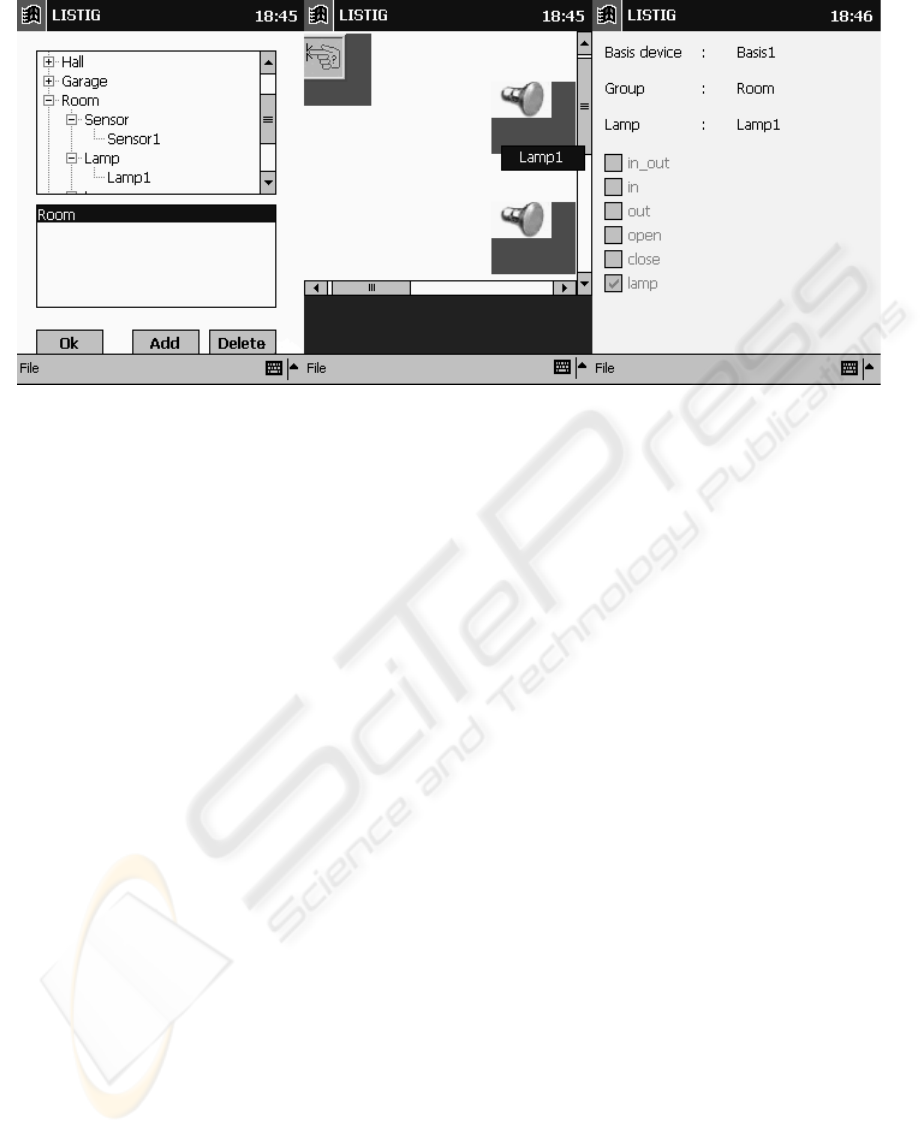
When the message reaches the terminal, the client
application parses the received XML string, installs
parameters of the objects, changes the colour of the
“addressed” objects to red (see figure 5) and notifies
the user with a voice message about the changes.
The costs of a LISTIG basis device is approxi-
mately 250$. It is not expensive but it can help peo-
ple to change their life for better with a new ad-
vanced technology.
5 SUMMARY AND FUTURE
TRENDS
In our project, we developed an integrated control
system for the smart home. The system works stably
and corresponds to the requirements of similar sys-
tems. The handling interface, especially developed
for communication between all components of this
system, is very simple and flexible. The client soft-
ware consists of a minimum of necessary elements
that effectively allow controlling the available
equipment. The security system is based on a pre-
sent-day well-known and reliable cryptographic al-
gorithm. The disadvantage of our software is that it
uses plenty of RAM memory. This is not very in-
convenient for PCs, but it plays a role for PDA’s
therefore the source code should be optimized.
There are many possibilities for improving the
client and server software. First of all the client
software should be divided into three groups: basis,
advanced and professional.
• Basis – for the end-users that can only ob-
serve the current state of the equipment.
They cannot change anything in the system
or they can enter some modifications accord-
ing to the authentication rights.
• Advanced – for the end-users that can control
and monitor well-defined equipment (for ex-
ample, not everyone has to have rights to
change the temperature in some specific
rooms).
• Professional – all rights in the system.
This division into three groups is rather common,
that is why there is no need to image something
novel.
It is also possible to allocate these three groups to
the server-software. Basis configuration allows link-
ing up sensors with well-defined actors and the user
cannot change this combination. Advanced configu-
ration allows freely linking the objects. With the
professional configuration the end-user has all pos-
sibilities. He can link up easily all events and use
output signals of control elements (actors) (as well
as a feedback). Furthermore additional objects are
available, for example timers etc.
And, of course, it is a very interesting task, as a
part of a scientific job, to build such an intelligent
and context-sensitive system. It considers wireless
communication such as WLAN, BLUETOOTH,
DECT etc. Thereby, one can locate the position of
the user inside of a building with the help of a PDA
or a Web PAD and the client software. It is not a
matter about localization in the world but localizing
the user in the current place of the building. For ex-
ample, when you enter a room you can see on the
screen of your PDA what is the room you have just
entered and all equipment that you can monitor and
control. It can be useful, for example, if you need to
Figure 5: Test application
A NEW VISION OF CONTROL FOR A SMART HOME
123

print some urgent papers but you don’t know exactly
the name of the room where you are now. With the
help of this intelligent technology you have to know
nothing about this room, you simply see this printer
on the screen and “take it easy”.
REFERENCES
Blumengarten, J., 2004. Home-Smart-Home.
http://www.pge.com/microsite/PGE_dgz/power/index.
htm
House, 2004. Haus der Gegenwart anlässlich der
Bundesgartenschau 2005 in München.
http://www.buga2005.de/de/besuch/veranstaltungsorte
/hausdergegenwart.shtml
Amigo, 2004. Amigo – Ambient intelligence for the
networked home environment. http://www.amigo-
project.org
DESOTRON, HFWK, 2003. LISTIG. LAN – integriertes
Steuerungssystem für intelligente Gebäudetechnik.
InnoRegio programme funded by the German Federal
Ministry of Education and Research (BMBF).
Technischer Antragsteil.
Prof. Dr. Müller, J., 2004. Objektorientiertes und
Ergebnisgesteuertes Automatisierungs- und
Kommunikationssystem für die dezentrale
Gebäudeautomation. Messezentrum Erfurt,
Informations- und Kommunikationssysteme zur
nachhaltig optimalen Gebäudenutzung. Symposium
2004.
Abascal, J., Hampicke, M., 2004. The publishing smart
homes – technology for the future company.
www.stakes.fi/cost219/procabascsmart3.doc
MARC, 2004. Smart in-home monitoring system.
http://marc.med.virginia.edu/projects_smarthomemoni
tor.html. Tec Home Builder Jan/Feb 2003.
Honeywell, 2003. Gebäudeautomation – Systemlösungen.
http://www.honeywell.at/index.php/g2,gebaude,sysl1
Berrimor, 2004. Intellectual system of control.
http://www.berrimor.ru/berrimor.html
WEBIST 2005 - INTERNET COMPUTING
124
