
FORMAL VERIFICATION OF TRANSACTIONAL SYSTEMS
Mark Song
Department of Computer Science - Centro Universit
´
ario UNA
Jose Claudio Resende, 80 - Cep 30455-590 - Belo Horizonte - Brasil
Adriano Pereira, Sergio Campos
Department of Computer Science - Universidade Federal de Minas Gerais
Av. Antonio Carlos, 6627 - CEP 31270-901 - Belo Horizonte - Brasil
Keywords:
web applications, design specification, model checking, formal verification, transformation patterns.
Abstract:
Today, the trend in software is toward bigger, more complex systems. This is due in part to the fact that
computers become more powerful every year leading users to expect more from them. People want software
that is better adapted to their need which, in turn, merely makes software more complex. This trend has
also been influenced by the expanding use of the internet for exchanging all kinds of information. As a new
computational infra-structure has become available, new distributed applications which were previously too
expensive or too complex have become common. In this context, web based systems has become a popular
topic for business and academic research. However, web applications tend to generate complex systems.
As new services are created, the frequency with which errors appear has increased significantly. This paper
presents the UML-CAFE, an environment which can be used to help the designer in the development of
transactional systems, such as web based ones. It is divided into the UML-CAFE Methodology, a set of
transformation patterns, and the UML-CAFE translator to describe and map UML specifications into a formal
model to be verified.
1 INTRODUCTION
Web based systems has changed the way organiza-
tions perform their activities. E-commerce systems,
for example, have simplified the access to goods and
services and has revolutionized the economy as a
whole. However, web based applications tend to
generate complex systems - transactional systems in-
volve concurrent operations which demand transac-
tional integrity. Besides, as new services are created
the frequency with which errors appear increase sig-
nificantly. Guaranteeing the correctness of such sys-
tems is not an easy task due to the great amount of
scenarios where errors may occur, many of them very
subtle. Such task is quite hard and laborious if only
tests and simulations, common techniques of system
validation, are used.
New approaches can be used in order to improve
the quality of the software and to guarantee the in-
tegrity of critical systems. Formal Methods (Huth
and Ryan, 2000) is one such approach. They con-
sist of the use of mathematical techniques to assist in
the documentation, specification, design, analysis and
certification of computational systems. Model check-
ing (Clarke et al., 1999), a special formal method ap-
proach, is sufficiently interesting and promising since
it consists of a robust and efficient technique to au-
tomatically verify the correctness of several system
properties, mainly regard to identification of faults
in advance. This paper presents an environment
that uses formal method techniques, a standard nota-
tion (the Unified Modeling Language - UML (OMG,
2003)), and a set of transformation patterns to design
and enable the automatic verification of transactional
systems, specially web based ones.
The paper is organized as follows. In Section 2, the
UML-CAFE environment is presented. Section 3 an-
alyzes the related works, and Section 4 presents some
conclusions and future work.
2 THE UML-CAFE
ENVIRONMENT
The UML-CAFE is an environment (Figure 1) which
can be used to help the designer in the development
of transactional systems, such as web based ones. It
is divided into the following components: the UML-
CAFE Methodology, a set of transformation patterns
194
Song M., Pereira A. and Campos S. (2005).
FORMAL VERIFICATION OF TRANSACTIONAL SYSTEMS.
In Proceedings of the First International Conference on Web Information Systems and Technologies, pages 194-197
DOI: 10.5220/0001227601940197
Copyright
c
SciTePress
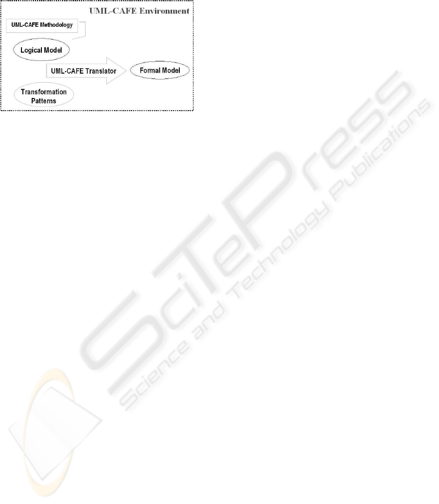
(used to describe and map UML specifications into
a formal model) and the UML-CAFE translator (a
tool which automatically translates the UML speci-
fications into the formal model to be verified).
Figure 1: The UML-CAFE Environment
2.1 Toward an Web Based System
Methodology
A successful development project satisfies or exceeds
the customer’s expectation, is developed in a timely
and economical fashion, and is resilient to change and
adaptation. The development, in general, proceeds as
a series of iterations that evolve into the final system.
Each iteration consists of one or more of the follow-
ing methodology components: requirements capture,
analysis, design, implementation, and test.
Usually, to build a complex system the developer
abstracts different views of it, builds models using
some notation, verifies that the models satisfy the re-
quirements, and gradually adds details to transform
the models into implementation. In this context, an
unified notation plays an important role once a sym-
bol can mean different things to different people.
In our work, it is adopted a general-purpose visual
modeling language (UML) to specify and construct
the artifacts of a software system. In order to trans-
late the UML specifications into formal model to be
verified, it has been proposed a set of transformation
patterns. The next subsection introduces our pattern
system.
2.2 Transformation Patterns
In software design, it is quite common not to solve
every problem from first principles. Expert designers
reuse solutions that have worked for them in the past.
When they find a good solution, they use it again and
again.
Consequently one can find recurring patterns in
many systems. These patterns solve specific de-
sign problems and make designs more flexible and
reusable. A designer who is familiar with such pat-
terns can apply them immediately to solve a problem.
2.3 The UML-CAFE Methodology
The UML-CAFE is a methodology to design trans-
actional applications with model checking support.
It is divided into four phases inherited from Formal-
CAFE (Pereira et al., 2002): conceptual, application,
functional, and execution. It can help the designer
to specify and verify the system under development.
The main idea of UML-CAFE is to detect and cor-
rect errors before they propagate to later stages. The
following subsections describe each phase of UML-
CAFE.
2.3.1 Conceptual Phase
The first phase which captures the requirements of the
system is divided into three stages:
Stage 1: In the first stage, the system is described
as a set of business rules.
Stage 2: Based on the business rules presented
in stage 1, the designer has to describe the actors,
their actions, the negotiated object and its states. The
designer builds the class diagram defining the static
structure of the model, in particular, classes and types,
their internal structure, and their relationships to other
classes. Each actor and the negotiated object is repre-
sented by a parameterized class.
Stage 3: At this point the designer describes in de-
tail the sequence of actions that each actor can exe-
cute. Actions are described by a transition graph as-
sociated to each class. The statechart shows the state
space of a given actor. Each state define an action that
can be executed. Transitions define a valid sequence
of operations that can be executed - a none state must
be defined to indicate that no action is under execu-
tion.
Note that the class diagram and associated action’s
graphs are used to generate the first version of the
model to be verified. Each parameterized class is
translated into a module in the formal model. Ac-
tions are represented by a variable named action and
each transition graph describes a change in the value
of the corresponding action variable. In this phase the
designer is able to verify if the business rules are spec-
ified correctly. For example, is it true that all actions
described can be executed? The designer applies the
completeness pattern in order to verify such fact:
• Name: Completeness Pattern.
• Intent: To verify if all possible values of an attribute are
modeled/achieved.
• Input: At(name, attribute, domain).
• Mapping: EF ( p )
Completeness( At(name, attribute, domain) )
Append( MODULE At.name )
repeat
FORMAL VERIFICATION OF TRANSACTIONAL SYSTEMS
195

select v in At.domain; mark v;
label ( SPEC EF (attribute = v ) )
until all v in At.domain is marked
The following code checks the completeness prop-
erties:
...
MODULE Actor
1
(id)
...
--Completeness Model Checking Pattern:
--EF (ACTION = <A>)
SPEC EF (action = action
1
)
...
SPEC EF (action = action
N
)
2.3.2 Application Phase
The second phase defines the behaviors of the system.
It describes the life cycle of the negotiated object, its
interactions with the actors and actions. Moreover,
the states are modeled and the system’s functionality
is described - a context diagram is presented. Proper-
ties, such as completeness and invariants, are verified.
At this phase, all elements are modeled through use
cases, as defined by the following stages:
Stage 4: Each use case is documented with a flow
of events required to accomplish its behaviors - a flow
of events is a sequence of transactions, or events, per-
formed by the system. It should contain detailed in-
formation written in terms of what the system should
do, regardless of how the system accomplishes the
task.
Stage 5: Here, the statechart diagram is used to
model the discrete stages of a system’s lifetime. The
statechart diagram shows the sequence of states that
the negotiated object goes through, the events that
cause a transition from one state to another, and the
actions that result from a state change.
Each state represents a snapshot during the life of
a system which satisfies some condition or waits for
some event. Transitions are represented by actions
which indicate the operation executed by an actor.
There is also a guard condition that must be met be-
fore the transition is taken. As long as the guard con-
dition remains false, the transition will not occur.
Stage 6: In this stage the developer reviews in
detail the precedent stages and collects, for each
use case, additional information such as invariant
and consistency properties. These properties are de-
scribed in the documentation section which is part of
the UML class specification.
The UML-CAFE has been designed to be an incre-
mental methodology. So, as the design evolves new
information must be added to the formal model. Mod-
ules are created and incrementally modified as the
design evolves. This is the main idea of the UML-
CAFE methodology - errors can be identified early in
the design and corrected before they propagate to later
stages. Again, the designer is able to verify if the de-
sign match the business rules specified. For example,
some business rules describe the consistency aspects
of the system - is it always true that if the system is
in a state where a property p is true than from now
on, q will be always true? Other rules specify the in-
variant aspects - is a property p always true? In time,
is there any state of the negotiated item that can not
be reached? The last one can be checked using the
completeness pattern. The consistency and invariant
patterns are used to model the other properties. The
following generated code checks the consistency and
invariant properties:
...
MODULE name(id, ...)
...
-- consistency Pattern:
-- AG ( expression
1
-> AG ( expression
2
) )
SPEC AG ( expr
1
-> AG ( expr
2
) )
...
-- Invariant Pattern: AG ( expr )
SPEC AG ( expr )
2.3.3 Functional Phase
This phase models the services provided by the sys-
tem. While each action comprises simple operations
such as allocating an item for future purchase, ser-
vices perform full transactions - actually, services are
sequences of actions. This phase is divided into three
stages:
• Stage 7: A set of services is defined for the use
cases previously identified. Now, each use case
is completed with a description for the service re-
quired.
• Stage 8: Once services are defined, the designer
describes the interaction among instances - the
UML sequence diagram is used to specify each ser-
vice.
• Stage 9: Each service consists of a sequence of
actions. Note that although actions are atomic by
definition, not every sequence of actions is atomic.
So, in this stage the services and their concurrent
aspects are described. The designer identify all se-
quences that must be executed isolated or consid-
ered as an atomic transaction.
Our experience pointed out that some concurrent
activities can not be fully described by sequence
diagrams. The isolation pattern can be used in this
phase to isolate conflicting services.
2.3.4 Execution Phase
The execution environment describes the interconnec-
tion between the components and the customers in-
WEBIST 2005 - INTERNET COMPUTING
196

terface. The definition of the execution environment
must be coherent with the description of the services
and functionalities that compose the functional phase.
This description must be done in terms of paradigms
of implementation, and system primitives. Examples
of paradigms are client-server, remote procedure calls
and message exchange. In this phase it is used physi-
cal diagrams such as deployment diagrams and com-
ponent diagrams - they are used to give descriptions
of the physical information about a system. Note that
business rules are not affected by the execution envi-
ronment. So, none additional checking must be done
in this phase.
3 RELATED WORK
Model checking has been successfully applied to the
verification of several large complex systems such as
an aircraft controller, a robotic controller, a distrib-
uted heterogeneous real-time system, and a multime-
dia application (Campos et al., 1999).
There is much interest in improving embedded sys-
tem functionalities, where security is a critical factor.
The use of softwares in this systems enable new func-
tionalities, but create new possibilities of errors. In
this context, formal methods might be good alterna-
tives to avoid them (Corbett et al., 2000).
In many software development phases, such as de-
sign and coding, complexity is addressed by the defi-
nition and use of abstractions (Fontoura et al., 2000).
For complex specification problems (Silva and Lu-
cena, 2004), abstraction is just as important. In our
work we define a set of transformation patterns so that
it can be applied to model checking of transactional
systems: the designer describes the elements of the
application using a modeling language (UML) (Song
et al., 2003) as defined in the UML-CAFE methodol-
ogy, and the elements of the model are automatically
projected into the formal model to be verified. Note,
that our approach does not demand that the designer
knows formal methods, nor it implies specific knowl-
edge in temporal logic.
4 CONCLUSIONS AND FUTURE
WORK
In this paper we propose a methodology to specify
and verify web based systems. This technique can
increase the efficiency of the design of web appli-
cations. We use a high level modeling language to
formalize the specification of the system and a set of
model checking patterns to map (automatically trans-
lation) the specifications into the formal model to be
verified. This approach can lead to more reliable,
less expensive applications that are developed signifi-
cantly faster.
We are currently studying other features of web
based systems that we have not yet formalized, as
well as the possibility of generating the actual code
that will implement the system from its specification.
REFERENCES
Campos, S., Ribeiro-Neto, B., Bertini, L., and Macedo, A.
(1999). Formal verification and analysis of multime-
dia systems. In Proceedings of the Seventh ACM Int.
Multimedia Conference (ACMMM’99), pages 131–
140, Orlando, FL.
Clarke, E. M., Grumberg, O., and Peled, D. A. (1999).
Model Checking. The MIT Press, Cambridge, Massa-
chusetts.
Corbett, J. C., Dwyer, M. B., Hatcliff, J., Laubach, S.,
P
˘
as
˘
areanu, C. S., Robby, and Zheng, H. (2000). Ban-
dera: extracting finite-state models from java source
code. In International Conference on Software Engi-
neering, pages 439–448.
Fontoura, M., Pree, W., and Rumpe, B. (2000). Uml-f:
A modeling language for object-oriented frameworks.
14th European Conference on Object Oriented Pro-
gramming (ECOOP 2000), pages 63–82.
Huth, M. R. and Ryan, M. D. (2000). Logic in Com-
puter Science - Modelling and reasoning about sys-
tems. Cambridge University Press.
Mota, E., Clarke, E., Oliveira, W., Groce, A., Kanda, J., and
Falcao, M. (2003). Veriagent: an approach to integrat-
ing uml and formal verification tools. In Proceedings
of the Sixth Brazilian Workshop on Formal Methods
(WMF’2003).
OMG (2003). Uml resource page.
http://www.omg.org/uml.
Pereira, A., Song, M., Gorgulho, G., Meira Jr., W., and
Campos, S. (2002). A formal methodology to specify
e-commerce systems. In Proceedings of the 4th Inter-
national Conference on Formal Engineering Methods,
Lecture Notes in Computer Science, Shanghai, China.
Springer-Verlag.
Silva, V. and Lucena, C. (2004). From a conceptual frame-
work for agents and objects to a multi-agent system
modeling language. In: Sycara, K., Wooldridge, M.
(Edts.), Journal of Autonomous Agents and Multi-
Agent Systems.
Song, M., Pereira, A., Lima, F., Gorgulho, G., Campos,
S., and Meira Jr., W. (2003). Extending uml to spec-
ify and verify e-commerce systems. In Proceedings
of the Fifteenth International Conference on Software
Engineering Knowledge Engineering, San Francisco,
USA.
FORMAL VERIFICATION OF TRANSACTIONAL SYSTEMS
197
