
The Cooperative Hunters — Efficient Cooperative
Search For Smart Targets Using UAV Swarms
⋆
Yaniv Altshuler
1
, Vladimir Yanovsky
1
, Israel A. Wagner
1,2
and Alfred M. Bruckstein
1
1
Computer Science Department, Technion, Haifa 32000 Israel
2
IBM Haifa Labs, MATAM, Haifa 31905 Israel
Abstract. This work examinestheCooperative Hunters problem, where a swarm
of UAVs is used for searching after one or more “smart targets” which are mov-
ing in a predefined area, while trying to avoid detection by the swarm. By ar-
ranging themselves into an efficient flight configuration, the UAVs optimize their
integrated sensing capability, and are thus capable of searching much larger ter-
ritories than a group of uncooperative UAVs. The problem was introduced in [1],
while similar work appears also in [4–7]. This work presents two decentralized
cooperative search algorithms which demonstrate major improvements over the
algorithm and analysis presented in [1]. The first algorithm uses improved flying
patterns which achieve superior search performance. An analytic optimality proof
for the algorithm’s performance is presented. The second algorithm is a fault tol-
erant algorithm which allows the UAVs to search in areas whose shapes and sizes
are unknown in advance (unlike the rectangular shapes only, in [1]). Due to space
constraints many technical and experimental details were omitted. Such details
will appear in a longer version of this work.
1 Introduction
Significant research effort has been invested during the last few years in design, analysis
and simulation of multi-agents systems design for searching areas (either known or
unknown) [4–7]. While in most works the targets are assumed to be idle, recent works
consider dynamic targets, meaning — target which by detecting the searching agents
from a long distance, try to avoid detection by evading the agents.
Such problem is presented in [1], where a swarm of UAVs is used for searching
after one or more evading “smart targets” (i.e. a platoon of T-72 tanks, a squad of sol-
diers, etc’). The UAVs’ goal is to find the targets in the shortest time possible. While
the swarm comprises relatively simple UAVs which lack prior knowledge of the initial
positions of the targets, the targets possess full knowledge of the whereabouts of the
swarm’s UAVs. The search strategy suggested in [1] defines flying patterns which the
UAVs will follow, which are designed for scanning the (rectangular) area in such a way
that the targets cannot re-enter sub-areas which were already scanned by the swarm,
without being detected by some UAV. Note that this protocol assumes that the area in
⋆
This research was partly supported by the Ministry of Science Infrastructural Grant No. 3-942
Altshuler Y., Yanovsky V., A. Wagner I. and M. Bruckstein A. (2005).
The Cooperative Hunters — Efficient Cooperative Search For Smart Targets Using UAV Swarms.
In Proceedings of the 1st International Workshop on Multi-Agent Robotic Systems, pages 165-170
DOI: 10.5220/0001193001650170
Copyright
c
SciTePress
which the targets can move is known to the UAVs in advance, and must be rectangular
in shape. Furthermore, the presented algorithm still requires a relatively high amount
of explicit cooperation between the UAVs, which can be obtained through the use of a
relatively high amount of communication.
This work presents two decentralized cooperative search algorithms which demon-
strate major improvements over the algorithm and analysis presented in [1]. The first
algorithm, discussed in section 2 uses improved flying patterns which enable the swarm
to achieve superior search performance. The optimality of this search scheme is proved
in section 2.3. The second algorithm, which is discussed in section 3 assumes no previ-
ous knowledge considering the area to be searched, and uses only a limited communi-
cation between the UAVs. The algorithm is also highly fault-tolerant, meaning — even
if many UAVs malfunction or be shot down, the swarm will still be able to complete the
task, albeit slower.
2 HUNT-I Algorithm — Optimality in Rectangular Shapes
Let N, D, S, L and W denote the number of UAVs, the sensor recognition diameter, the
line formation’s scan width, the length of the rectangular region and the width of the
rectangular region, respectively (note that S = N · D). Let V and v denote the speeds
of the UAVs and the targets respectively.
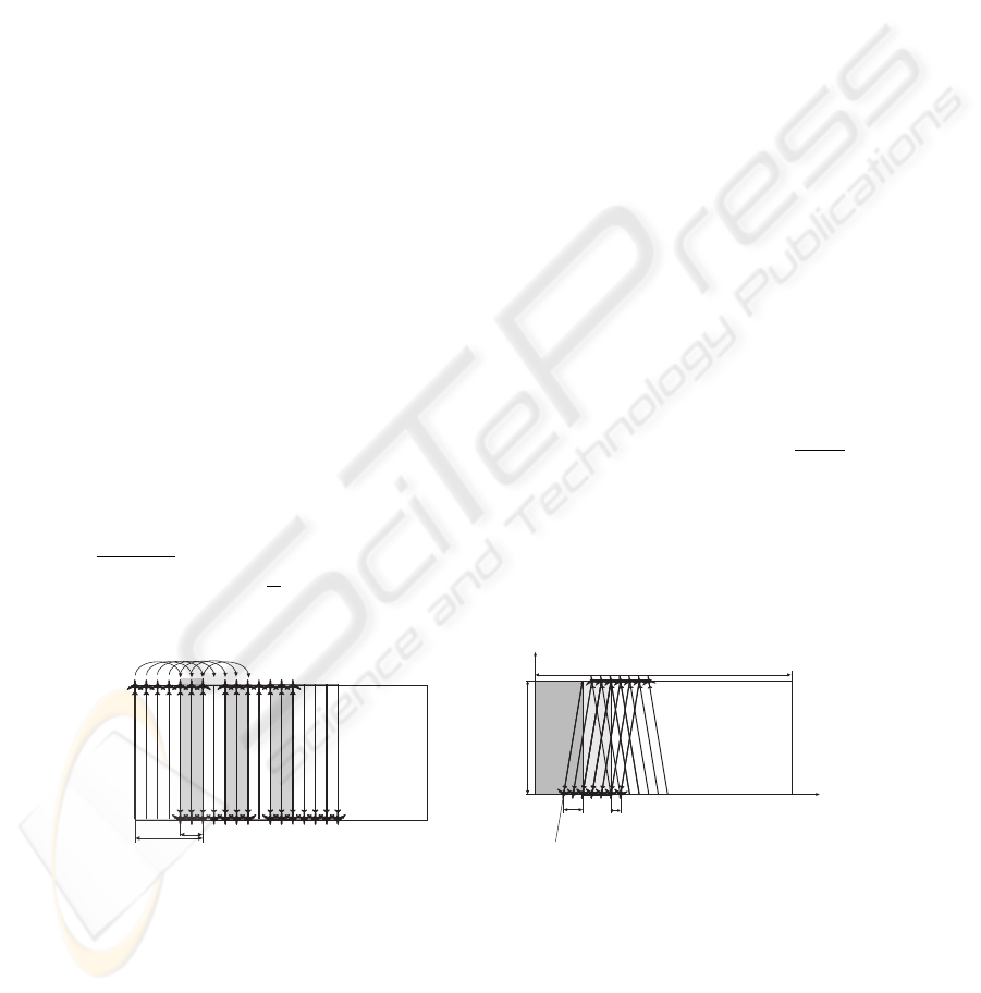
In the algorithm of [1] the UAWs were designed to fly upwards and downwards in
line formations parallel to the boundary of the region. In order to ensure that no target
escapes into an already clean area, the rectangles formed by consecutive sweeps must
overlap. Fig. 2 illustrates the algorithm. W.l.o.g., suppose S = 1. Since it takes
2W +a
V
for the UAVs to go to from one side of the rectangle to the opposite side, shift rightwards
a and return, in order to ensure that the target do not move into an already cleared
region while the UAVs are away, the rectangular scan bands need to have overlap of size
(2W +a)·v
V
. Since the overlap’s width is at most 1, the algorithm of [1] cannot complete
the mission in case
V
v
≤ 2W .
S
B
W
L
Y
X
P
a
vt
V
t
Fig.1. Illustration of the algorithm from Wincent et al. [1] (on the left) and our improved algo-
rithm (on the right).

2.1 Description of the Algorithm
Next, we show an algorithm that can guarantee locating the targets even if
V
v
≥ W + 1.
Similarly to the algorithm of [1] we use upwards and downwards sweeping by a line
formation of UAVs (as illustrated in Fig. 2). Again, we assume that S = 1.
Before each sweeping pass, the UAVs are placed in a line at either top or bottom side
of the rectangle. In Fig. 2 we show two sweeping passes. Before the first and after the
second pass the planes are at the top side of the rectangle (a light-gray rectangle shows
the addition to the clean area after the two passes). The line formation first moves from
BC to AD. Before the stage begins at time t = 0, the area to the left of line BF ,
filled with dark gray in Fig. 2, is already clean. Point A to which the left edge of UAV
formation heads is chosen such that
|AB|
V
=
|AF |
v
. Denote T =
|AB|
V
=
|AF |
v
.
Lemma 1. When the formation reaches the lower side of the rectangle at time t = T ,
the region to the left of line DJ is clean.
Proof. We separate the proof into two parts:
1. – No target can move to the left of line AB. Suppose a target crosses the line at
point Q. By the choice of A, if at time t = 0 the target was in Q ∈ [BF ] and
the UAV at B, they reach location Z, where Z is such that ZQ is parallel to
axis X, simultaneously and the target will not cross AB undetected.
– If the target attempts to cross line AB at Z
′
(or Z
′′
), then it will not be able to
do this, since even a target located in Q
′
(or Q
′′
) at t = 0 is not able to do this
despite been nearer to Z
′
(or Z
′′
), respectively, than Z.
2. A target cannot move into ABJD. Indeed if it waits at line JD till the UAV forma-
tion passes and then heads leftwards, by the choice of point A the target will reach
line JD at the same time as the formation reaches the bottom side of the area.
When the formation is at the segment AD, it needs to shift rightwards to occupy
segment EG such that the area to the left of E is clean. Hence E is chosen such that
|AE|
V
=
|ED|
v
. This completes the description of one pass of the algorithm — as before
the pass started when the region to the left of E is clean.
2.2 Analysis of the Algorithm
In this section we shall analyze the behavior of the algorithm for different values of V ,
v and W . First, let us see for which ratio
V
v
, given W , the algorithm succeeds.
Lemma 2. If
V
v
≥ W + 1 the formation is able to move forward.
Proof. In order for the algorithm to be able to move forward by some a > 0 the UAVs
formation must be able to shift from AD to EG faster than the “target contaminated
front” moving from DJ to KE. Hence, it must hold that
|AF |+a
V
>
|F D|−a
v
, when A is
such that
|BA|
V
=
|F A|
v
. That is, for the maximal possible propagation A we have:
W
2
+ (vT )
2
= (V T )
2
v t+a
V
=
1−v t−a
v
(1)

After some tedious calculations and denoting r =
V
v
we get:
a(r, W ) =
r
r + 1
−
W
√
r
2
− 1
(2)
If r is such that a(r, W ) > 0, the algorithm is able to complete the mission. Follow-
ing some more computations we obtain a simpler looking lower bound on propagation
after a single pass (Hence, for r ≥ W + 1 the propagation is positive):
a(r, W ) >
r
r + 1
(1 −
W
r − 1
) (3)
Using the original notations, given a sensor recognition diameter D, y ≥ W + 1 is
equivalent to the condition on the number of UAVs sufficient to guarantee completion:
N =
W
(r − 1)D
(4)
This can be compared to the bound from Wincent et al. [1] :
N =
2W
rD
(5)
A
B
Z’’
P
Z’
Z
Q
F
Q’
Q’’
Fig.2. Illustration of a target attempting to cross into already clean region.
2.3 Lower Bound on the Number of UAVs — Optimality Proof
After we found in the previous section that if r ≥ W + 1, mission completion is guar-
anteed, we would like to prove the following Lemma.
Lemma 3. If r < W , the UAVs will not be able to complete the mission, independently
of the algorithm they use.
Proof. Given an algorithm, denote with C(t) the convex hull of the region guaranteed
to be clean of targets at time t, by S(t) denote its area, and let us consider
∂S
∂t
. We show
that if t is such that S(t) =
LW
2
,
∂S
∂t
< 0, proving that the algorithm will not be able to
complete the mission. Denote with P (t) the length of the circumference of C(t) that is
not part of the rectangle’s boundary. F rom geometric considerations, it can be seen that
S(t + ∆t) − S(t) < ∆t S · V − ∆t P (S(t)) · v (6)

Recalling our assumption S = 1, we have:
∂S
∂t
≤ v · r(r − P (S(t))) (7)
If we prove that for t
0
s.t. S(t
0
) =
LW
2
it holds that P (S(t
0
)) ≥ W , the claim
of the Lemma will follow from the assumption W > r. The proof of the later is by
consequently applying elementary geometric arguments to the cases of C(t) having
common points with 1 to 4 sides of the rectangle and is omitted. For instance, if C(t
0
)
has common points with one side of the rectangle, then the circumference of C(t) is
at most 2P (t
0
) ≤ 2W . Since of all shapes with the same area a circle has the greatest
area, S(t
0
) ≤
W
2
π
<
W
2
2
.
3 HUNT-II Algorithm — Simplicity and Robustness
Although the initial problem is that of searching for hiding targets within a given area,
we shall consider an alternative, yet equivalent problem — the dynamic cooperative
cleaners problem. The static variant of the cooperative cleaners problem is described
and analyzed in [2], while the dynamic variant of the problem appears in [3]. This prob-
lem assumes a grid, part of which is ‘dirty’, where the ‘dirty’ part is a connected region
of the grid. On this dirty grid region several agents move, each having the ability to
‘clean’ the place it is located in. The dynamic variant involves a deterministic evolution
of the environment, simulating a spreading contamination (or fire).
Notice that from a cleaning protocol which is used by agents in order to solve the
cooperative cleaners problem, a protocol for the swarm search problem can be derived.
This is done by defining the entire area G as ‘contaminated’. A ‘clean’ square (either
a square which has not been contaminated yet, or a square which was cleaned by the
UAVs) will represent an area which is guaranteed not to contain any target. By using
the fact that the contamination is spreading, we simulate the fact that the targets may
manoeuver around the UAVs, in order to avoid detection — if vertex v is contaminated
then it may contain a target, thus, after
1
v
target
time steps this target could have moved
from v to its neighbors, had it been in v (when v
target
is the speed of the targets). As
a result, after
1
v
target
time steps all the neighbors of v become contaminated. In other
words, the spreading contamination acts as a danger diffusion which simulates the ca-
pability of a square to contain a target. The agents’ goal is to eliminate the contaminated
area — eliminate the places which the targets may be hiding in. Once there are no longer
squares in which the targets may be hiding, the swarm is guaranteed to have detected
all evading targets. Note that our demands regarding no prior knowledge of the search
area are met, since the cooperative cleaners problem do not assume such knowledge.
3.1 Swarm Search Algorithm
Let each UAV i hold G
i
— a bitmap of G. Let every G
i
be initialized to zeros (e.g.
“clean”). Let each UAV i contain a hash table of vertices — f
i
which for every vertex
can return on or off. The default for all the vertices is of f . The list f
i
represents the
vertices which are known to be within the area to be searched.

Every time a UAV flying over vertex v identifies v or one of its neighbors to be a
part of the area to be searched, if f
i
(v) = off it sets the corresponding vertices of G
i
to
1, sets f
i
(v) to be on, and broadcasts this information to the other UAVs. Once a UAV
receives a transmission that vertex v is part of the area to be searched, it sets f
i
(v) to
on and sets the corresponding vertex in G
i
to 1. Every time a UAV moves it broadcasts
the direction of its movement to the rest of the UAVs (north, south, west or east).
Notice that every time step each UAV broadcasts the new squares which are parts
of G (which are set to 1 in G
i
), and the squares it “cleaned” by flying over them (which
are set to 0). Thus, the G
i
and f
i
of all UAVs are kept synchronized. Since v
target
is known to the UAVs, they can simulate the spreading contamination, by performing
(∀v ∈ G
i
, ∀u ∈ Neighbors(v) : state(u) = 1) every
1
v
target
time steps. Thus, the
bitmaps G
i
always represent the correct representation of the area still to be cleaned.
The direction of movement and the decision whether or not to clean a vertex are
determined using some cleaning protocol (for example, the SWEEP protocol of [3]).
Notice that all the analytic bounds over the cleaning time of a cleaning protocol are
immediately applicable for our hunting protocol. Whenever a UAV cleans a certain
vertex, it sets this vertex in G
i
to be 0, and broadcasts this information. Once a UAV
receives such a transmission, it sets the vertex corresponding to the new location of the
transmitting UAV to 0.
The UAVs are assume to be placed on the boundary of the area to be searched. Thus,
each G
i
immediately contains at least one vertex whose value is 1. As a result, for G
i
to contains only zeros, the UAVs must have visited all the vertices of G and had made
sure that no target could have escaped and “re-contaminated” a clean square. When G
i
becomes all zeros UAV i knows that the targets have been found, and stops searching.
Since each time step, each UAV can move in at most 4 directions (i.e. 2 bits of
information), clean at most a single vertex (i.e. 1 bit of information), and broadcast the
status of 8 neighbor vertices (i.e. 3 bits of information), the communication is limited
to 6 bits of information per UAV per time step.
References
1. Vincent, P., Rubin, I.: “A Framework and Analysis for Cooperative Search Using UAV
Swarms”, ACM Simposium on applied computing, (2004).
2. Wagner, I.A., Bruckstein, A.M.: “Cooperative Cleaners: A Case of Distributed Ant-
Robotics”, in “Communications, Computation, Control, and Signal Processing: A Tribute
to Thomas Kailath”, Kluwer Academic Publishers, The Netherlands, pp. 289–308, (1997).
3. Altshuler, Y., Bruckstein, A.M., Wagner, I.A.: “Swarm Robotics for a Dynamic Cleaning
Problem”, in “IEEE Swarm Intelligence Symposium 2005”, pp. 209–216, (2005).
4. Passino, K., Polycarpou, M., Jacques, D., Pachter, M., Liu, Y., Yang, Y., Flint, M. and Baum,
M.: “Cooperative Control for Autonomous Air Vehicles”, In Cooperative Control and Opti-
mization, R. Murphey and P. Pardalos, editors. Kluwer Academic Publishers, Boston, (2002).
5. Stone, L.D: “Theory of Optimal Search”, Academic Press, New York, (1975).
6. Koopman, B.O: “The Theory of Search II, Target Detection”, Operations Research 4, 5,
503–531, October, (1956).
7. Koenig, S., Liu, Y.: “Terrain Coverage with Ant Robots: A Simulation Study”, AGENTS’01,
May 28–June 1, Montreal, Quebec, Canada, (2001).
