
COORDINATION OF A PROTOTYPED MANIPULATOR BASED
ON AN EXPERIMENTAL VISUO-MOTOR MODEL
Renato de Sousa Dâmaso, Mário Sarcinelli Filho, Teodiano Freire Bastos Filho
Department of electrical engineering, Federal University of Espírito Santo, Av. Fernando Ferrari, 514, Vitória, Brazil
Tarcisio Passos Ribeiro de Campos
Department of nuclear engineering, Federal University of Minas Gerais, Av. Antônio Carlos, 6627, Belo Horizonte, Brazil
Keywords: Visuo-motor coordination, Control of manipulators, Object grasping, Uncalibrated binocular vision.
Abstract: This paper presents a strategy to build an experimental visuo-motor model for a manipulator coupled to a
binocular vision system, which discards any previous algebraic model and any calibration of either the
manipulator or the vision system. The space spanned by a set of selected image features is divided in
regions, and the estimated visuo-motor model is represented by a matrix of constant elements associated to
each one of such regions. Such matrices are obtained in an incremental way, starting from commands of
movement and using the measurements of the variations they cause in the set of image features. Even when
partially filled in, the visuo-motor model can be used for coordinating the manipulator in order to get its
end-effector closer to an object and to grasp it. Preliminary results got from the implementation of the
proposed strategy in a prototyped manipulator coupled to a binocular vision system are also presented.
1 INTRODUCTION
Typical methods for the visual servo-control of
manipulators to grasp objects use analytical models
previously established, thus demanding the
knowledge of the geometry, of the mechanical and
of the optical system parameters, as it is exemplified
in Dâmaso et al. (2003). Transformations from the
articulate space of the manipulator to the global
inertial space, from this to the coordination system
associated to the cameras, and, finally, from the last
to the coordination systems of the image planes are
accomplished. These procedures result in a nonlinear
matrix transformation, called Jacobian matrix
(Hutchinson et al., 1996). However, in many real
situations, this model may be too difficult to obtain.
In situations not requiring critical system
performance, like to grasp static objects or objects
moving slowly, it becomes interesting to estimate
models starting from sending movement commands
to the joints of the manipulator and measuring the
variations of certain visual cues (Hollinghurst and
Cipolla, 1994; Graefe, 1995; Xie et al., 1997). A
control system with these features would have the
capability of learning through its own experiences,
becoming able to approach a near object and to
grasp it. It is also desirable that the estimation of a
visuo-motor model can be completed as quickly as
possible (what means with just a few motion
examples) in a non-supervised way. Other desirable
characteristics such a system should exhibit are the
capability to “remember” what was learnt in
previous experiments, like it is recommended in
Graefe (1995), and the capability to "re-learn", so
that it can adapt the model to eventual changes.
In previous works, Hollinghurst and Cipolla (1994)
applied an affine stereo formulation to estimate a
matrix relating, qualitatively, the articulation’s
positions of the manipulator to a fixed point position
in its claw onto both images. Such a matrix was used
in an object grasping task, matching position and
orientation. Hosoda and Asada (1997) proposed an
adaptive control strategy based on the on-line
estimation of the Jacobian matrix, with no a priori
knowledge of the kinematics and the parameters of
the camera-manipulator system as well. This
estimation was iteratively performed, and it was
assumed that the coefficients did not converge to the
true values of the Jacobian matrix. However, the
estimation was precise enough, in addition to the
closed loop control, to guide the manipulator when
304
de Sousa Dâmaso R., Sarcinelli Filho M., Freire Bastos Filho T. and Passos Ribeiro de Campos T. (2005).
COORDINATION OF A PROTOTYPED MANIPULATOR BASED ON AN EXPERIMENTAL VISUO-MOTOR MODEL.
In Proceedings of the Second International Conference on Informatics in Control, Automation and Robotics - Robotics and Automation, pages 304-309
DOI: 10.5220/0001191303040309
Copyright
c
SciTePress
following previously defined paths. By their turn,
Xie, Graefe and Vollmann (1997) apply a procedure
based on attempting and error, which is described in
(Graefe, 1995), to guide the end-effector to an
object. After each attempting, only the articulated
positions corresponding to the position of the object
in the image planes were stored. After several
attempts, the stored information was used to obtain
the articulate coordinates corresponding to a non-
recorded position of the object, through the
interpolation of neighbouring positions.
In this paper, a direct process to estimate the matrix
relating the motor actions to the corresponding
variations in a set of image features is investigated.
By analogy with the visual servoing procedure, the
estimated visuo-motor matrices (Ĥ) is associated to
the function carried out by the Jacobian matrix, or
imend
qH
.
ˆ
&
&
=
ξ
, (1)
where
⎥
⎥
⎥
⎦
⎤
⎢
⎢
⎢
⎣
⎡
=
333231
232221
131211
ˆ
hhh
hhh
hhh
H
, (2)
end
ξ
&
is a vector containing the variations in the
image features of the end-effector,
im
q
&
is a vector
containing the velocities of the motors and h
ij
are the
coefficients of Ĥ (i and j vary from 1 to 3,
hereinafter).
As it will become clearer ahead, this matrix
constitutes a linear approach for the visuo-motor
correlation, which is a nonlinear one. Thus, the
matrix Ĥ only represents an "acceptable" approach
in an area close to the one in which the coefficients
have been estimated. To overcome this limitation,
the space spanned by the set of selected image
features is divided in areas, and a data structure is
created to store the matrix Ĥ relative to each area
(coefficients of Ĥ locally distributed).
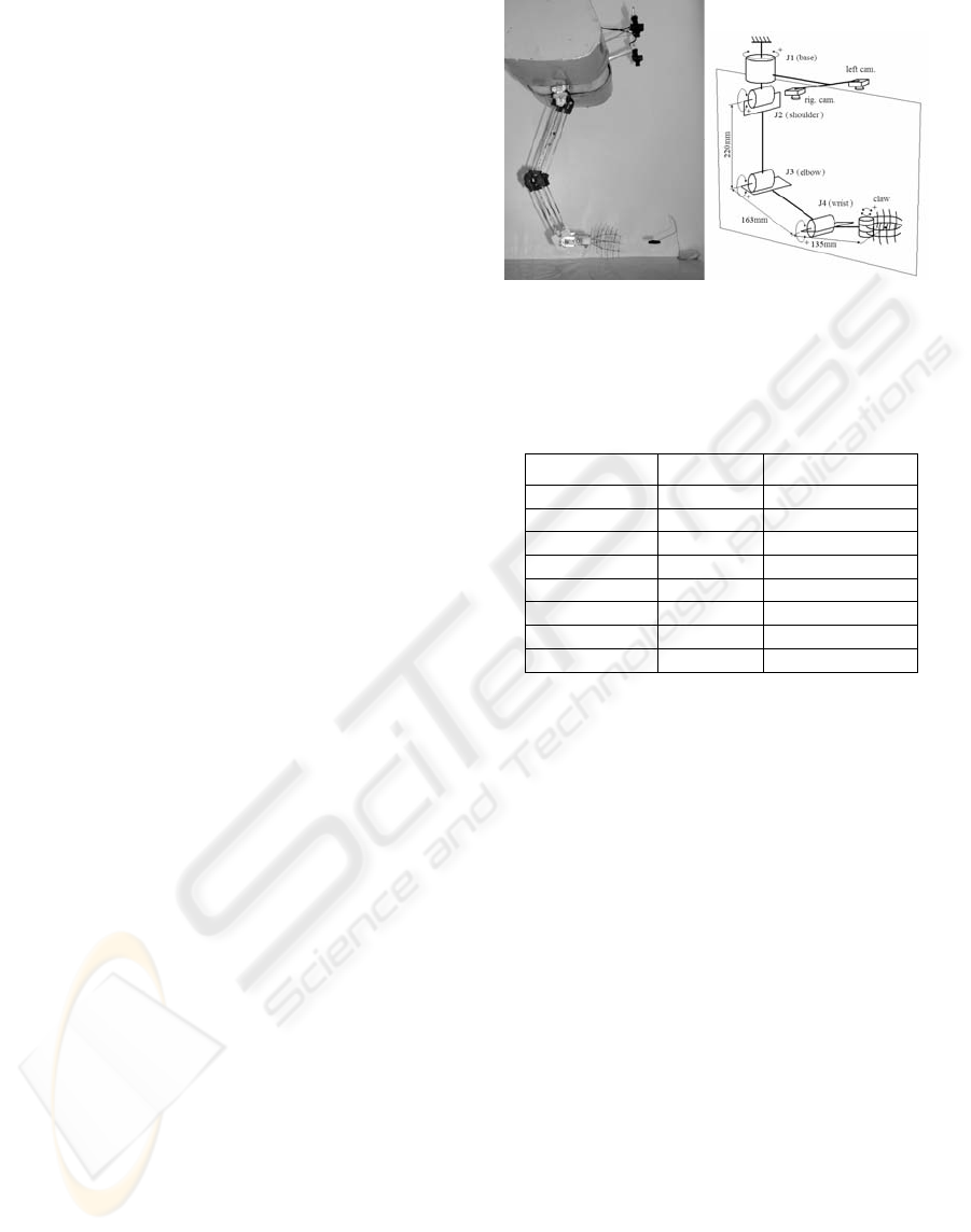
2 EXPERIMENTAL PLATFORM
The system used for testing the strategy under
analysis, based on an incremental visuo-motor
model, is shown in Figure 1. A sketch of the
kinematical chain of the manipulator prototype is
also shown. The vision system, also represented in
Figure 1, is composed of a pair of cameras attached
to the manipulator base. The positive direction
adopted for the movement of each joint is also
indicated in Figure 1. The corresponding motors are
driven to one of the eight speed levels indicated in
Table 1, in degrees per second.
Table 1: The set of values of the speed levels for each
motor in the manipulator
Speeds
1m
q
&
[°/s]
52
,,
mm
qq
&&
⋅⋅⋅
[°/s]
level 0 0 0
level 1 9,0 36,9
level 2 13,8 54,9
level 3 18,5 73,4
level 4 24,3 98,1
level 5 31,2 126,0
level 6 43,7 176,4
level 7 54,8 220,5
Both cameras are analogues, and are oriented such
that their optical axes are close to parallel. Two
frame grabbers are installed in a computer, called
control computer, to acquire the images delivered by
the cameras. The image-processing algorithms
allowing extracting the characteristics of interest,
which are executed in the control computer,
complete the experimental setup employed.
A small dark parallelepiped (26 mm x 24 mm x 8
mm) is used as object (considered as a punctual
object. The coordinates of the centroid of such
object in the image planes are measured by the
vision system, whose sampling period is 100 ms.
3 THE PROPOSED STRATEGY
The procedure presented in the sequence is based on
visual information, and corresponds to two modes: i)
Perception, involving the estimation of the
coefficients that relate the space of motion
commands to the space spanned by the selected
image features; and ii) Action (or Coordination),
including the transformation of the visuo-motor
information estimated in the previous step to signals
effectively acting on the system to coordinate the
Figure 1: A view of the manipulator prototype and the
two cameras of the vision system, and its structure
COORDINATION OF A PROTOTYPED MANIPULATOR BASED ON AN EXPERIMENTAL VISUO-MOTOR
MODEL
305
articulated structure of the manipulator for
accomplishing the task of interest.
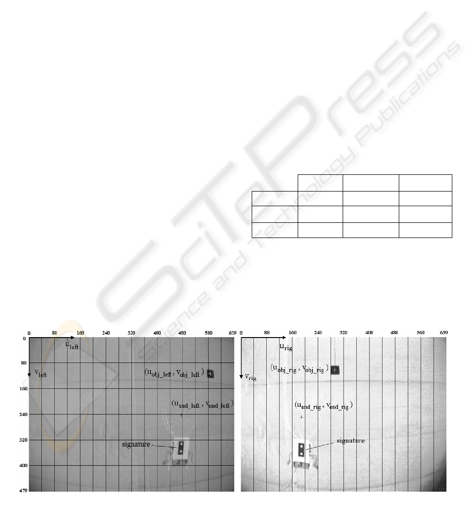
Figure 2 shows a pair of binocular images, on which
the axes u and v of the coordinate systems associated
to the left and right image planes are indicated. The
image features measured by the vision system
(Damaso et al., 2004) are also pointed out. To
control the first three DOF of the manipulator (to
control the position of its end-effector related to the
object), the following variables were selected
T
rigendleftendleftendend
uvu ] , ,[
___
=
ξ
(3)
T
rigobjleftobjleftobjobj
uvu ] , ,[
___
=
ξ
. (4)
The position of the robot end-effector is defined by
the coordinates of a hypothetical point, marked as +
in the image planes. A signature was used to allow
finding such hypothetical point, as depicted in
Figure 2. It is a black rectangle with two white balls,
and is fixed to the robot end-effector (Dâmaso et al.,
2003). The abscissa of the hypothetical point is
equal to the abscissa of the centroid of the white ball
having the smallest ordinate. The ordinate of the
hypothetical point is equal to the ordinate of such
centroid less four times the Euclidian distance
among the centroids of both white balls.
The possible values of the
ξ
end
components,
generically given by the dimensions of the image
planes (640 by 480 pixels), define a three-
dimensional space of characteristics (domain). The
division of this domain in areas or cells is proposed,
as represented in the image planes shown in Figure
2. The same procedure is applied to
ξ
obj
, which
conveys information about the object, in relation to
the base movements, with the difference that the
intervals in u
left
and u
rig
were chosen as being twice
bigger (see in Figure 3). The smaller number of cells
associated to the variations of the base articulation
(J1) can be justified by the fact that the movements
of such articulation do not produce significant
variations in the object depth. Thus, the values of
ξ
end
and
ξ
obj
address the cells in which the end-
effector and the object are placed, respectively. In
each cell, the estimated coefficients are constant.
Starting from the selected image features, the
variables (
∆
error_u,
∆
v_end_left,
∆
disp_end) were
defined, as follows,
2/)( _
____ rigendrigobjleftendleftobj
uuuuuerror −
+
−
=
, (5)
leftend
vleftendv
_
__
=
, (6)
rigendleftend
uuenddisp
__
_ −=
. (7)
Such variables represent the variations generated
during a fixed time interval. They are suitable to
express the movement of the end-effector or the
object in the image planes and in depth, once u
end_left
and u
end_rig
present very close variations for the
camera configuration (parallel optical axes).
Then, Table 2 is generated, which is used to estimate
the coefficients h
ij
of Ĥ, regarding the time interval
∆
t during which the movement is performed.
Table 2: Coefficients of the transformation matrix
∆
error_u
∆
v_end_left
∆
disp_end
tq
m
∆
⋅
3
&
h
11
h
21
h
31
tq
m
∆
⋅
2
&
h
12
h
22
h
32
tq
m
∆
⋅
1
&
h
13
h
23
h
33
3.1 Visuo-Motor Model Estimation
After being moved to the initial position, similar to
the position illustrated in Figure 2, the manipulator
is commanded to move the joint J2 (shoulder). The
Figure 2: Example of a pair of images of the binocular arrangement, showing the image coordinate systems (in pixels), the
selected image features and the splitting of the space spanned by the image features for the end-effector
ICINCO 2005 - ROBOTICS AND AUTOMATION
306

image features at the beginning and at the end of the
movement are measured and the coefficients
⎟
⎟
⎠
⎞
⎜
⎜
⎝
⎛
∆⋅
∆
=
∆⋅
∆
=
∆⋅
∆
=
tq
enddisp
h
tq
leftendv
h
tq
uerror
h
mmm 2
32
2
22
2
12
_
,
__
,
_
&&&
(8)
are evaluated. The joint J2 is then pulled back to its
initial position, procedure that is repeated for J3 and
J1. Regarding the movement of the joint J1, as the
cameras are fixed to the manipulator base, it does
not result in any change in the position of the end-
effector in the image planes. Thus, it is necessary
that the object stays stopped in the space during an
experiment on the "Perception" mode, serving as a
reference to the base movements (landmark). It is
used the correspondence that the end-effector
movement, in this case, is equal to the inverse of the
object movement in the image planes, for the
calculation of the coefficients h
13
, h
23
and h
33
. It
should be observed that the position of the object is
not learnt, and the object can (actually it should) be
put in different positions on the running of various
experiments.
At the end of this initial training step, all the
coefficients of Ĥ would be estimated for the initial
positions of the manipulator and the object, thus
allowing knowing how to move the manipulator in a
rough way. Continuing in the "Perception" step, the
end-effector is commanded to get progressively
closer to the object, while allowing moving just one
of the first three joints in each iteration, in an
alternate way. For doing that, the control system
verifies if the coefficients h
11
, h
21
and h
31
of the
transformation matrix corresponding to the
addressed cell were not estimated, sending an
actuation command to the joint J3. Case this
estimation has been already performed, it verifies if
the parameters h
12
, h
22
and h
32
are missing, and sends
an actuation command to joint J2 if affirmative.
Finally, if the coefficients of both lines have already
been estimated, it alternates the commands of J3 and
J2. The articulation J1 is commanded between the
command of J3 and J2, since the movement of either
J3 or J2 does not change the position of the object.
Thus, new columns of coefficients of Ĥ are
generated and stored in the corresponding cells. If
there is a previous value for the estimated
coefficient, they are averaged with the new values,
before being updated. At the end of each
experiment, the columns of coefficients of the
transformation matrix in the data structures are
copied to files, thus allowing saving values which
are loaded to the data structures in the beginning of
another experiment, giving to the system the ability
of memorizing any estimated model.
3.2 Visuo-Motor Coordination
The values stored in the two data structures of the
incremental visuo-motor model can be used to
coordinate the manipulator. At the "coordination"
step the first three articulations of the manipulator
can be commanded simultaneously, together with J4,
which is moved in order to keep the claw
approaching the horizontal. In this step, however,
there will be no estimation of the coefficients of Ĥ.
The manipulator is initially commanded to its initial
position. The image features are measured, and it is
verified if all the coefficients of the cell addressed
by the end-effector ((h
11
, h
21
, h
31
) and (h
12
, h
22
, h
32
))
and the coefficients of the cell filled by the object
(h
13
, h
23
, h
33
), were estimated. If this has not
happened, the coefficients associated to the last
totally filled area that the manipulator and the object
passed by are adopted. This is a solution that
degrades the performance of the estimated model,
but it is expected to be very seldom when a great
number of experiments is run at the "Perception"
mode for various positions of the object placed on
the space of interest.
The desirable variations in the image features are
obtained starting from the expressions of
proportional control action. This means that
uerrorKuerror __
1
⋅
=
∆
, (10)
leftverrorKleftendv ____
2
⋅=∆
, (11)
disperrorKenddisp __
3
⋅
=
∆
, (12)
with
leftendleftobj
vvleftverror
__
__
−
=
, (13)
enddispobjdispdisperror _ _ _ −=
, (14)
rigobjendobj
uuobjdisp
__
_
−
=
. (15)
The proportional gains were experimentally
adjusted, resulting in K
1
= 0.20, K
2
= 0.22 and K
3
=
0.22. Then, the speeds of the motors corresponding
to the articulations are calculated through the
solution of the linear equations (
∆
t is 1 s)
⎪
⎩
⎪
⎨
⎧
∆=⋅+⋅+⋅
∆=⋅+⋅+⋅
∆=⋅+⋅+⋅
enddispqhqhqh
leftendvqhqhqh
uerrorqhqhqh
mmm
mmm
mmm
_
__
_
133232331
123222321
113212311
&&&
&&&
&&&
. (16)
Finally, each evaluated speed is match to one of the
speed levels shown in Table 1. The control system
recalculates the reference speeds in an interval of 0.5
s, until the characteristic errors are smaller than the
following thresholds (in pixels): (|error_u| = 10, -20
COORDINATION OF A PROTOTYPED MANIPULATOR BASED ON AN EXPERIMENTAL VISUO-MOTOR
MODEL
307
< error_v_left < 0, |error_disp| = 8). Thus, the end-
effector gets close to the object, and the grasping
step starts, with the end-effector moving towards the
object at the same time its claw starts closing.
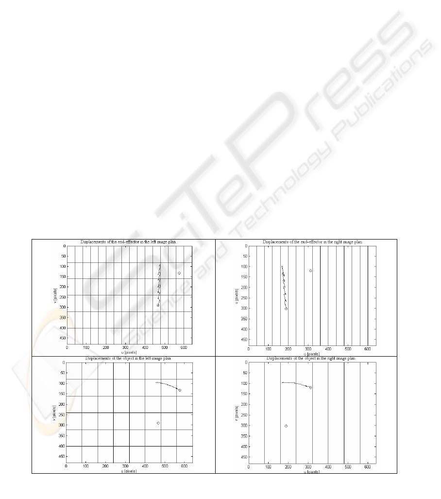
4 EXPERIMENTAL RESULTS
Aiming at an initial evaluation of the proposed
strategy, it was programmed in the experimental
platform. How the image characteristics associated
to the end-effector and to the object vary in the
image planes, for an experiment for estimating the
visuo-motor model (“Perception” mode), is shown in
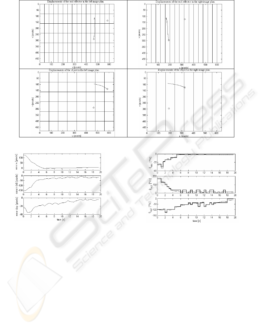
Figure 3. Figure 4, by its turn, presents these
movements for an experiment in the “Action” mode.
The initial positions of the interest pictures were
denoted by circles. The displacements of the end-
effector and of the object take place in an alternate
way for the "Perception" mode (Figure 3), and
simultaneously for the "Action" mode (Figure 4).
For the presented coordination experiment, the
curves showing how the characteristic errors very
are shown in Figure 5. The curves representing the
calculated speeds, by their turn, are shown in Figure
6, with the curves of the approximated speeds. It can
be observed, especially in the beginning of this
experiment, that the depth of the end-effector is
modified by the movements of the joints J2 and J3,
making the disparity error to increase. This variation
is corrected along the experiment.
5 CONCLUSIONS AND FUTURE
WORK
In this paper a strategy to incrementally build a
visuo-motor model for a manipulator with an
uncalibrated binocular vision system is proposed.
The main points of this proposition are the form the
coefficients of the visuo-motor transformation
matrix (Ĥ) are estimated and the segmentation of the
space spanned by a group of image features in
smaller areas. As a consequence of both such a
partition and the fact that the cameras are fixed to
the manipulator base, it resulted a data structure
related to the end-effector, intended to store the
coefficients ((h
11
, h
21
, h
31
) and (h
12
, h
22
, h
32
)) of Ĥ for
each cell, and other data structure, addressed by the
object position, to store (h
13
, h
23
, h
33
). In the
"Perception" mode, just an articulation is
commanded each time, and the estimated
coefficients are used to continuously update the
stored values. The two data bases are stored in files,
so that they can be used from an experiment to other.
In the "coordination" mode, by its turn, the
articulations are moved simultaneously, using the
visuo-motor model previously obtained.
The results so far obtained show that it is indeed
possible to coordinate the motion of the manipulator
joints, using such approach, in order to get closer to
an object and to grasp it.
Figure 3: The displacement of the end-effector and the object for an experiment in the "Perception" mode, and the
splitting of the spaces spanned by the image features associated to the end-effector and to the object
ICINCO 2005 - ROBOTICS AND AUTOMATION
308
REFERENCES
Dâmaso, R. S., Campos, T. P. R., Bastos-Filho, T. F. and
Sarcinelli-Filho, M., 2004. Coordenação Visuo-
Motora de um Manipulador Experimental: Uma
Abordagem Reativa, In XV Congresso Brasileiro de
Automatica, Gramado, Brazil, in CD (in Portuguese).
Dâmaso, R. S., Carelli, R., Bastos-Filho, T. F. and
Sarcinelli-Filho, M., 2003. Controle Servo Visual de
um Manipulador Industrial Auxiliado por Visão
Binocular. In VI Simpósio Brasileiro de Automação
Inteligente, Bauru, Brazil, pp.799-803 (in Portuguese).
Graefe, V., 1995. Object- and Behavior-oriented Stereo
Vision for Robust and Adaptive Robot Control,
International Symposium on Microsystems, Intelligent
Materials, and Robot, Sendai, Japan, pp. 560-563.
Hollinghurst, N., Cipolla, R., 1994. Uncalibrated Stereo
Hand-Eye Coordination, Image and Vision
Computing, vol.12(3), pp. 187-192.
Hosoda, K., Asada, M., 1997. Adaptive Visual Servoing
for Various Kinds of Robot Systems, V International
Symposium on Experimental Robotics (V ISER),
Barcelona, Spain, pp. 451-462.
Hutchinson, S., Hager, G., Corke, P., 1996. A Tutorial on
Visual Servo Control, IEEE Transactions on Robotics
and Automation, vol.12, pp. 651-670.
Xie, Q., Graefe, V., Vollmann, K., 1997. Using a
Knowledge Base in Manipulator Control by
Calibration-Free Stereo Vision, IEEE International
Conference on Intelligent Processing Systems, China.
Figure 6: Calculated (thin lines) and approximate speeds
(thick lines) for an example in “Coordination” mode
Figure 4: The displacements of the end-effector and the object for an experiment in the "Coordination" mode
Figure 5: Error evolution for an example i
n
“Coordination” mode
COORDINATION OF A PROTOTYPED MANIPULATOR BASED ON AN EXPERIMENTAL VISUO-MOTOR
MODEL
309
