
ACTIVE STEREO VISION-BASED MOBILE ROBOT NAVIGATION
FOR PERSON TRACKING
V. Enescu, G. De Cubber, K. Cauwerts, S. A. Berrabah, H. Sahli
Vrije Universiteit Brussel
Pleinlaan 2, B-1050 Brussels, Belgium
M. Nuttin
Katholieke Universiteit Leuven
Celestijnenlaan 300B, B-3001 Heverlee-Leuven, Belgium
Keywords:
active vision, person following, color tracking, particle filter, proposal distribution, mean shift, measurement
model update, robot navigation, fuzzy logic behavior-based navigation, hybrid behavior-based navigation.
Abstract:
In this paper, we propose a mobile robot architecture for person tracking, consisting of an active stereo vision
module (ASVM) and a navigation module (NM). The first tracks the person in stereo images and controls the
pan/tilt unit to keep the target in the visual field. Its output, i.e. the 3D position of the person, is fed to the
NM, which drives the robot towards the target while avoiding obstacles. As a peculiarity of the system, there
is no feedback from the NM or the robot motion controller (RMC) to the ASVM. While this imparts flexibility
in combining the ASVM with a wide range of robot platforms, it puts considerable strain on the ASVM.
Indeed, besides the changes in the target dynamics, it has to cope with the robot motion during obstacle
avoidance. These disturbances are accommodated by generating target location hypotheses in an efficient
manner. Robustness against outliers and occlusions is achieved by employing a multi-hypothesis tracking
method - the particle filter - based on a color model of the target. Moreover, to deal with illumination changes,
the system adaptively updates the color model of the target. The main contributions of this paper lie in (1)
devising a stereo, color-based target tracking method using the stereo geometry constraint and (2) integrating
it with a robotic agent in a loosely coupled manner.
1 INTRODUCTION
In the past, robot navigation was commonly based
upon data coming from classical sensory equipment
like ultrasonic and infrared sensors or laser range
scanners. This approach is in sharp contradiction with
nearly all biological examples (e.g. humans) where
vision is the primary sensing modality. This biologi-
cal example inspired scientists (Beardsley et al., 1995;
Davison and Murray, 1998) to tackle the visual nav-
igation problem and, during the last decade, visual
navigation has gained significant importance.
The main problem in setting up a global control
architecture for a mobile robot with an active vision
control loop is that the frequency of the robot con-
trol loop (and certainly that of an eventual manipula-
tor installed on the mobile agent) differs from the fre-
quency of the vision control loop. This also leads to a
second problem: the reusability of the developed con-
trol architecture on different robotic platforms. Due
to the difficulties with the timing between different
loops in the systems, most researchers (Davison and
Murray, 1998) tune their control processes such that
they work well for one specific robot. Unfortunately,
the high coupling between the visual and the robot
control loop yields a robot-dependent control archi-
tecture.
In this paper, we set up a global system architecture
for a visually guided robot, which is independent from
the specific robot hardware and kinematics. We do
this by separating the visual processing (ASVM), the
navigation control (NM) and the robot motion con-
troller (RMC). As an application for such a robotic
system, we chose the person following task, for which
several problems have to be solved: person tracking,
coping with the erratic motion of the target, stereo
head control, 3D position estimation, robot naviga-
tion and the robot motion control. In the following,
we address each of these problems.
For most tracking applications a Kalman filter is
used, as it is a reliable and efficient tool. As a disad-
vantage, the Kalman filter can not handle multi-modal
distributions as present in our problem. Therefore, we
resort to particle filtering, a Monte Carlo method able
to maintain multiple hypotheses about the target state
in the presence of non-linearity and non-Gaussian dis-
32
Enescu V., De Cubber G., Cauwerts K., A. Berrabah S., Sahli H. and Nuttin M. (2005).
ACTIVE STEREO VISION-BASED MOBILE ROBOT NAVIGATION FOR PERSON TRACKING.
In Proceedings of the Second International Conference on Informatics in Control, Automation and Robotics - Robotics and Automation, pages 32-39
DOI: 10.5220/0001187300320039
Copyright
c
SciTePress
turbances.
In general, the motion of the target in a target track-
ing scheme is modeled using a predefined model such
as a constant speed or a constant acceleration model
(Strens and Gregory, 2003). This leads to problems
when humans need to be tracked, as they could have
both models as well as unpredictable motions. There-
fore, to cater for the erratic target motion, we propose
an effective mechanism for generating target location
hypotheses in the particle filter. Based on the current
estimate of the system state, a PID controller deter-
mines the control signal to be applied to the pan/tilt
stereo head to keep it aligned with the target.
For the 3D position estimation, some authors (Ping
et al., 2001) use scaling as means to retrieve depth
information, while others (Ghita and P.-F., 2003) use
the depth from defocus measure. The most popular
approach is however to make use of a stereo setup to
estimate the distance to a target (Arsenio and Banks,
1999; Schlegel et al., 2000; Kuniyoshi and Rougeaux,
1999; Wilhelm et al., 2004). This is also the method
we use here.
In the context of robot navigation, many algorithms
have been proposed to solve the path planning prob-
lem, ranging from simple potential field methods (Ko-
ren and Borenstein, 1991) to biologically inspired
neural networks (Franz and H.-A., 2000). We opted
for a behavior based control architecture for the navi-
gation module.
The RMC requires careful consideration of the ro-
bot kinematics and dynamics. As we wanted to build
a system which is easily portable from one robot sys-
tem to another, we decoupled the platform-dependent
RMC from the ASVM and NM. The RMC is there-
fore not considered part of the system architecture and
is not pursued further.
The remainder of this paper is organized as fol-
lows. First, an overview of the system architecture
is given in Section 2. Then, in Section 3, the active
vision module is extensively explained. Here the top-
ics of color histogram matching, stereo geometry, the
particle-filter based target tracking and camera control
are discussed. The navigation module is introduced in
Section 4, after which, in Section 5, we present some
results. Finally, we conclude the paper in Section 6.
2 OVERVIEW
To achieve the task of person following, two main
problems need to be solved:
• The vision system has to track the target person
• The robot has to navigate to the target person with-
out bumping into obstacles
In fact, these two problems can both be considered as
a coordinate system alignment problem. This can be
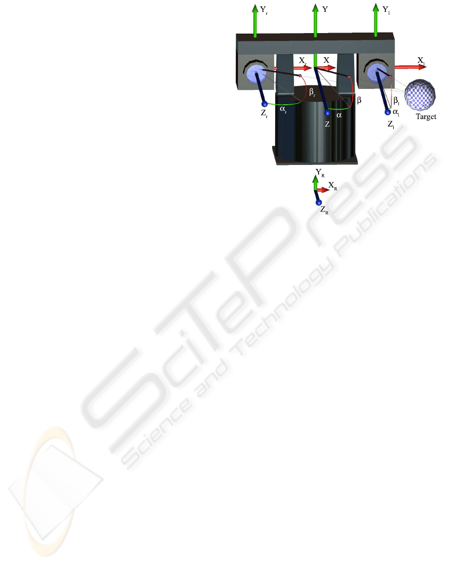
Figure 1: Definition of the coordinate systems: (OXY Z) is
the stereo head coordinate system, (O
l,r
X
l,r
Y
l,r
Z
l,r
) is the
left/right camera coordinate system, and (O
R
X
R
Y
R
Z
R
) is
the robot camera coordinate system.
explained using Figure 1. The objective of the visual
tracking system is to align the coordinate system of
the stereo camera such that the Z-axis points straight
at the target, thus minimizing the relative pan and tilt
angles of the stereo vision system, α and β respec-
tively. On the other hand, the objective of the robot
is to move towards the goal, and hence to align the
robot coordinate system such that the Z
R
-axis points
straight at the target. This is in general not the case
due to the movement of the target person, the inertia
of the robot and because the robot has to avoid ob-
stacles on its way. Thus, most of the time, α
R
> 0,
where α
R
= ∠(O
R
Z
R
, OZ). To be able to navigate
in a complex environment with obstacles, a behavior
based robot navigation was adopted, where one be-
havior leads the robot to the target, whereas another
behavior enables the robot to avoid obstacles.
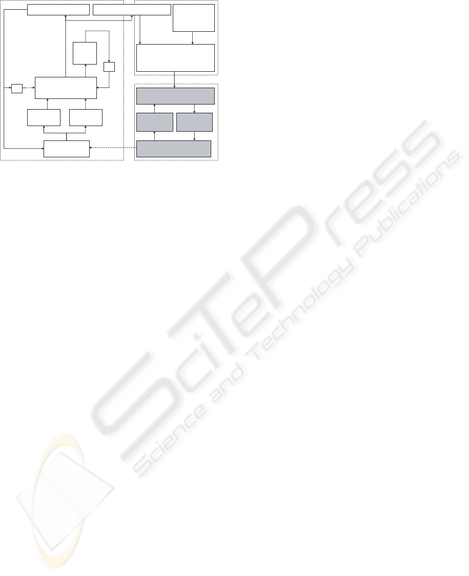
The general system architecture which integrates
all the capabilities discussed above is sketched in
Figure 2. On the left, one can observe the ASVM,
which receives its input from the two cameras in-
stalled on the stereo head. At the heart of ASVM
is a particle filter-based visual tracker which gener-
ates at each time step hypotheses (particles) about the
3D target position (in spherical coordinates) relative
to the (XY Z) frame. These hypotheses are ”pro-
jected” onto the image plane, resulting in a set of
candidate target regions within the left and right im-
ages. For each pair of candidate regions, we com-
pute two color histograms which we compare with
ACTIVE STEREO VISION-BASED MOBILE ROBOT NAVIGATION FOR PERSON TRACKING
33
Stereo Head
Camera 1 Camera 2
Color based target
tracker using particle
filtering
Pan & Tilt Controller
Target
Model
Update
Navigation Controller
Motion Controller
Motor
Controller
State
Observer
Robot Actuators & Odometry
Proprioceptive
and
exteroceptive
sensors
Z
-1
Z
-1
3D Target Position Estimation
Active Stereo Vision Module (ASVM) Navigation Module (NM)
Robot Motion Controller (RMC)
Figure 2: Overview of the system architecture
the base color histograms (left and right) serving as
model for the tracked person. The likelihood of each
hypothesis is then quantified by the matching degree
between these histograms. The outcome of the track-
ing process is an estimate of the target position in the
form of a probabilistic mixture of the target hypothe-
ses. This estimate consists of the azimuth (ˆα), ele-
vation (
ˆ
β), and range (
ˆ
λ) of the target and its use is
threefold. First, it serves for updating the base color
histograms in view of coping with changing illumi-
nation conditions. Second, the target pose estimate is
fed to the pan & tilt controller, which employs two
PID controllers to ensure smooth and robust stereo
camera control. Finally, the estimate is used to re-
cover the absolute 3D position (relative to the robot
frame) of the target person. This position estimator
links the ASVM to the NM (see Figure 2). There, a
navigation controller will distill a heading direction
and speed from the absolute pan angle (i.e. α
R
+ ˆα),
the target range (
ˆ
λ) and the input from the propriocep-
tive and exteroceptive sensors. We have tested differ-
ent behavior-based navigation controllers: a simple
dual-behavior fuzzy logic-based navigation controller
and a more elaborate hybrid architecture consisting
of a deliberative and a reactive part. The final output
on this level of the robot navigation module, a head-
ing direction and a speed setpoint, is compatible with
most robotic platforms, no matter what their kinemat-
ics and dynamics are. What follows further are robot-
specific modules, indicated by the shaded blocks in
Figure 2, which are not part of the presented architec-
ture.
3 ACTIVE VISION
The ASVM accomplishes the following tasks:
1. tracking the 3D position of a person over time by
means of the color properties of a region of his
body; the color model of the target is updated in
time to account for the variations in illumination;
2. control of the stereo head such that the person stays
always in the field of view of the stereo head;
These tasks are detailed in the sequel of this section.
3.1 Dynamic model
The state of the target at time k is described by the
vector x
k
= (α
k
, β
k
, λ
k
) containing the spherical
coordinates of the target with respect to the frame
(OXY Z) attached to the stereo head. α is the az-
imuth angle relative to OZ, β is the elevation angle
relative to the plane (OXY ), and λ is the target range.
Since a person may move in an unpredictable way,
we adopt a weak state evolution model (inspired by
(P
´
erez et al., 2004)) for the stereo head-target system.
More specifically, we assume that the state vector
components evolve according to mutually indepen-
dent Gaussian random walk models, which we aug-
ment with uniform components to capture the possi-
bly erratic motion of the target. Thus the state evolu-
tion model can be written as
p(α
k
|α
k−1
) = ϕ
1
N (α
k
; α
k−1
+ cu
p
k−1
, σ
2
1
)
+ (1 − ϕ
1
)U(α
k
; −α
m
, α
m
)
(1)
p(β
k
|β
k−1
) = ϕ
2
N (β
k
; β
k−1
+ cu
t
k−1
, σ
2
2
)
+ (1 − ϕ
2
)U(β
k
; −β
m
, β
m
)
(2)
p(λ
k
|λ
k−1
) = ϕ
3
N (λ
k
; λ
k−1
, σ
2
3
)
+ (1 − ϕ
3
)U(λ
k
; λ
min
, λ
max
)
(3)
where u
p
k
and u
t
k
are the pan and tilt control inputs,
c is a known coefficient, {ϕ
i
}
3
i=1
∈ (0, 1) are known
mixing coefficients, N (x; µ, σ
2
) denotes a Gaussian
distribution of variable x, mean µ, and variance σ
2
,
and U(x; x
min
, x
max
) signifies that x is uniformly
distributed between x
min
and x
max
. Note that σ
1,2,3
,
α
m
, β
m
, λ
min
and λ
max
are known by design. Since
α
k
, β
k
, λ
k
are independent variables, it follows that
the state evolution distribution factorizes as :
p(x
k
|x
k−1
) = p(α
k
|α
k−1
)p(β
k
|β
k−1
)p(λ
k
|λ
k−1
).
(4)
3.2 Stereo Geometry
The geometry of the stereo vision system is sketched
in Figure 1. We track the 3D position of the target rel-
ative to the frame XY Z, (α, β, λ), using color mea-
surements in the image plane. Hence, we need to find
a relationship between (α, β, λ) and the 2D position
of the point where the target projects on the image
plane, for each image in a stereo pair. To this end, a
ICINCO 2005 - ROBOTICS AND AUTOMATION
34

first step is to compute the azimuth and elevation an-
gles of the target with respect to the coordinate frame
attached to each camera, i.e. (α
l
, β
l
) for the left image
and (α
r
, β
r
) for the right image. As this derivation is
identical for α and β, we only present the solution for
the azimuth angles here. From (Vieville, 1997, p. 30),
we have that
α
l,r
= arctan
u
0
+ f
tan(α) ∓
b
2λ cos(α)
(5)
where u
0
is the optical center of the camera, b is the
baseline and f is the focal length.
Now, we shall relate (α
l
, β
l
, α
r
, β
r
) to the posi-
tion of the target projection in each image. Let p
l
=
(u
l
, v
l
) and p
r
= (u
r
, v
r
) denote the position of the
target projection on the left image I
l
and on the right
image I
l
, respectively. Given the geometry of the im-
age formation, the following relations hold:
u
l,r
= f · D
u
· tan(α
l,r
) (6)
v
l,r
= f · D
v
· tan(β
l,r
) (7)
where D
u
and D
v
represent the number of pixels
per meter in horizontal and vertical direction, respec-
tively. Thus, starting from (α, β, λ), we can deter-
mine p
l
and p
r
based on (5), (6), and (7). Let
(p
l
, p
r
) = T2S(α, β, λ)
(T2S stands for ”3D to stereo”) be the function corre-
sponding to these transformations. It is useful to also
define S2T (), the inverse function of T2S():
(α, β, λ) = S2T(p
l
, p
r
), (8)
Alternatively, we refer to T2S as ”projection” and to
S2T as ”back-projection.”
3.3 Color-based measurement model
Initially, at time k = 0, the projections of the target
on the image planes are delineated manually and de-
scribed by means of two elliptical regions with the
half axes H
u
and H
v
. Let these regions be denoted
by R
l,0
= R(p
l,0
, 1) (in the left image) and R
r,0
=
R(p
r,0
, 1) (in the right image), where R(p, s) is an
elliptical region of center p and scale factor s with
respect to the initial ellipse (H
u
, H
v
). Subsequently,
tracking the object throughout the stereo image se-
quence localizes the object at time k within the re-
gions R
l,k
= R(p
l,k
, s
k
) and R
r,k
= R(p
r,k
, s
k
),
where s
k
is the scale at time k. Note that the scale of
the object in the image is inverse proportional with λ
and therefore can be estimated by
s
k
= λ
0
/λ
k
, (9)
where λ
0
is initial target range and is found by back-
projecting p
l,0
and p
r,0
.
The appearance of a target confined to the image
region R(p, s) is described by means of a spatially-
weighted color (RGB) histogram (Comaniciu et al.,
2003) with B bins:
h
R
(u) = c
X
r∈R
φ
kr − pk
H
δ[b(r)−u], u = 1, ..., B
where c is a constant such that
P
B
u=1
h(u) = 1, b(r)
is a function mapping the color of the point r into
a color bin, H = s
p
H
2
u
+ H
2
v
, and φ is the kernel
function
φ(r) =
1 − r
2
, r < 1
0, otherwise
(10)
The target model consists of the color histograms of
the elliptic regions R
l,0
and R
r,0
. For simplicity, let
these histograms be denoted by
q
l
(u) , h
R
l,0
(u), q
r
(u) , h
R
r,0
(u) (11)
For k > 0, the similarity between the target model
q and the color model h of a target candidate (in one
image) is assessed using the Bhattacharya distance,
defined as
d[q, h] =
p
1 − ρ[q, h], (12)
where ρ[q, h] =
P
B
u=1
p
q(u)h(u).
The Bayesian estimation paradigm entails speci-
fying the likelihood function p(z
k
|x
k
) of the state
x
k
given the measurement z
k
. Note that, in our
case, the measurement consists of color stereo im-
ages, z
k
= {I
l,k
, I
r,k
}. Dropping the time index k
for convenience, the likelihood can be expressed as
p(I
l
, I
r
|x) = p(I
l
, I
r
|α, β, λ) = p(I
l
|∆, I
r
)p(I
r
|∆),
(13)
where ∆ , (p
l
, p
r
, s) and (p
l
, p
r
) = T2S(x). For
the partial likelihood p(I
r
|∆), we use the formulation
from (Perez et al., 2002)(Nummiaro et al., 2003):
p(I
r
|∆) = p(I
r
|R(p
r
, s)) ∝ exp
−
d
2
[q
r
, h
R
r
]
2σ
2
r
,
(14)
where d is given by (12) and σ
2
r
is a design parameter
which plays the role of a measurement error variance.
The image correlation likelihood p(I
l
|∆, I
r
) quan-
tifies the matching between the Bhattacharya distance
in the left and right image and is modeled here as a
Gaussian function of the distance difference:
p(I
l
|∆, I
r
) = p(I
l
|R(p
l
, s), R(p
r
, s), I
r
)
∝ exp
−
(d[q
l
, h
R
l
] − d[q
r
, h
R
r
])
2
2σ
2
c
(15)
where σ
c
is a design parameter. Plugging (14) and
(15) into (13) yields
p(I
l
, I
r
|x)
∝ exp
−
d
2
[q
r
, h
R
r
]
2σ
2
r
−
(d[q
l
, h
R
l
] − d[q
r
, h
R
r
])
2
2σ
2
c
(16)
ACTIVE STEREO VISION-BASED MOBILE ROBOT NAVIGATION FOR PERSON TRACKING
35
3.4 Particle filter algorithm
For non-linear, non-Gaussian and multi-modal mod-
els, as the one described here, the particle filter (Aru-
lampalam et al., 2002) provides a Monte Carlo solu-
tion to the recursive filtering equation p(x
k
|z
1:k
) ∝
p(z
k
|x
k
)
R
p(x
k
|x
k−1
)p(x
k−1
|z
1:k−1
) necessary for
tracking. Starting with a weighted particle set
{(x
(i)
k−1
, ˜w
(i)
k−1
)}
N
i=1
approximately distributed ac-
cording to p(x
k−1
|z
1:k−1
), the particle filter proceeds
by predicting new samples from a suitably chosen
proposal distribution which may depend on the old
state and the current and previous measurements, i.e.
x
(i)
k
∼ q(x
k
|x
(i)
k−1
, z
1:k
). To maintain a consistent
sample, the new particle weights are set to
w
(i)
k
∝
p(z
k
|x
(i)
k
)p(x
(i)
k
|x
(i)
k−1
)
q(x
(i)
k
|x
(i)
k−1
, z
1:k
)
˜w
(i)
k−1
. (17)
After weight normalization, the new particle set
{(x
(i)
k
, ˜w
(i)
k
)}
N
i=1
is then approximately distributed
according to p(x
k
|z
1:k
). The particles are resampled
according to their weights to avoid degeneracy.
Particle filters suffer from the curse of dimension-
ality, i.e., as the dimension of the state-space in-
creases an exponentially increasing number of parti-
cles is required to maintain the same estimation ac-
curacy. To mitigate this phenomenon, we choose a
proposal density which biases the generation of the
particles towards the most-likely 3D location, while
it maintains predictive particles to handle the back-
ground clutter and recover from failure or tempo-
rary occlusion. More specifically, q(x
k
|x
k−1
, z
1:k
)
is a mixture between the state evolution distribu-
tion, p(x
k
|x
k−1
), and a Gaussian distribution whose
mean (ˆα
ms
k
,
ˆ
β
ms
k
,
ˆ
λ
ms
k
) is derived via stereo mean-
shift tracking and back-projection:
q(x
k
|x
(i)
k−1
) = (1 − γ)p(x
k
|x
(i)
k−1
) + γN
3
(x
k
) (18)
where γ ∈ (0, 1) is a mixing factor. The mean-shift
algorithm (Comaniciu et al., 2003) minimizes (12),
thereby finding a highly possible location of the target
in the image. The coefficient γ expresses our belief in
the mean-shift derived 3D target hypotheses, sampled
according to the density
N
3
(x
k
) = N (α
k
; ˆα
ms
k
, σ
2
)N (β
k
;
ˆ
β
ms
k
, σ
2
)
· N (λ
k
;
ˆ
λ
ms
k
, σ
2
).
(19)
The vector (ˆα
ms
k
,
ˆ
β
ms
k
,
ˆ
λ
ms
k
) is obtained as follows:
starting from the mean target positions in the left and
right image at time k − 1,
ˆ
p
l
(k − 1) and
ˆ
p
r
(k − 1),
we find via mean-shift the positions of the target at
time k, respectively
ˆ
p
ms
l
(k) and
ˆ
p
ms
r
(k), in the cur-
rent stereo images I
l
and I
r
. Further, from these two
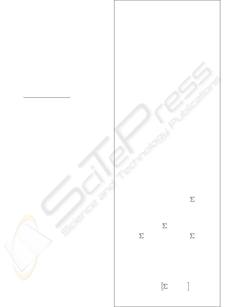
Given the sample set S
k−1
= {(x
(i)
k−1
, ˜w
(i)
k−1
)}
N
i=1
at time k − 1, obtain S
k
= {(x
(i)
k
, ˜w
(i)
k
)}
N
i=1
as follows:
1. Importance sampling. For i = 1, . . . N , sample x
(i)
k
based on x
(i)
k−1
and q(x
k
|x
k−1
, z
1:k
):
• mean shift tracking and back-projection:
ˆ
p
ms
l
= MeanShift(
ˆ
p
l
(k − 1), I
l
)
ˆ
p
ms
r
= MeanShift(
ˆ
p
r
(k − 1), I
r
)
(ˆα
ms
,
ˆ
β
ms
,
ˆ
λ
ms
) = S2T(
ˆ
p
ms
l
,
ˆ
p
ms
r
)
• sample u ∼ U(u; 0, 1)
• if u > γ, sample x
(i)
k
= (α
(i)
, β
(i)
, λ
(i)
) as follows:
α
(i)
∼ p(α
k
|α
(i)
k−1
) [see eq. (1)]
β
(i)
∼ p(β
k
|β
(i)
k−1
) [see eq. (2)]
λ
(i)
∼ p(λ
k
|λ
(i)
k−1
) [see eq. (3)]
else, sample x
(i)
k
= (α
(i)
, β
(i)
, λ
(i)
) as follows:
α
(i)
∼ N (α
k
; ˆα
ms
, σ
2
) [see eq. (19)]
β
(i)
∼ N (β
k
;
ˆ
β
ms
, σ
2
) [see eq. (19)]
λ
(i)
∼ N (λ
k
;
ˆ
λ
ms
, σ
2
) [see eq. (19)]
• project x
(i)
k
to the image locations p
(i)
l
, p
(i)
r
:
(p
(i)
l
, p
(i)
r
) = T2S(α
(i)
, β
(i)
, λ
(i)
), s
(i)
= λ
0
/λ
(i)
• compute w
(i)
k
, the unnormalized weight of x
(i)
k
, ac-
cording to (17,4,16,18); the likelihood p(I
l
, I
r
|x
(i)
k
) =
p(I
l
, I
r
|p
(i)
r
, p
(i)
l
, s
(i)
) (16) is computed based on the
histograms
h
(i)
r
, h
R
r
(u), where R
r
= R(p
(i)
r
, s
(i)
) ⊂ I
r
h
(i)
l
, h
R
l
(u), where R
l
= R(p
(i)
l
, s
(i)
) ⊂ I
l
2. Weight normalization: ˜w
(i)
k
= w
(i)
k
/
N
i=1
w
(i)
k
3. Estimation. Compute the mean state of the set S
k
, the
scale estimate, and the mean target positions in the left
and right image:
ˆ
x
k
= (ˆα
k
,
ˆ
β
k
,
ˆ
λ
k
) =
N
i=1
˜w
(i)
k
x
(i)
k
, ˆs
k
= λ
0
/
ˆ
λ
k
,
ˆ
p
l
(k ) =
N
i=1
˜w
(i)
p
(i)
l
,
ˆ
p
r
(k ) =
N
i=1
˜w
(i)
p
(i)
r
4. Target model update. Compute the occlusion/outlier
indicator o = p(I
l
|
ˆ
p
l
, ˆs) + p(I
r
|
ˆ
p
r
, ˆs) as the sum of
likelihoods (defined by(14)) of the elliptical regions of
scale ˆs, centered at
ˆ
p
l
and
ˆ
p
r
respectively; if o exceeds
a threshold th
1
, we proceed to the target model update
(see Section 3.5).
5. Selective resampling: if the effective sample size
N
ef f
=
N
i=1
( ˜w
(i)
k
)
2
−1
is below a threshold th
2
, apply a systematic resampling
step - see (Arulampalam et al., 2002).
Figure 3: Particle filter algorithm
ICINCO 2005 - ROBOTICS AND AUTOMATION
36
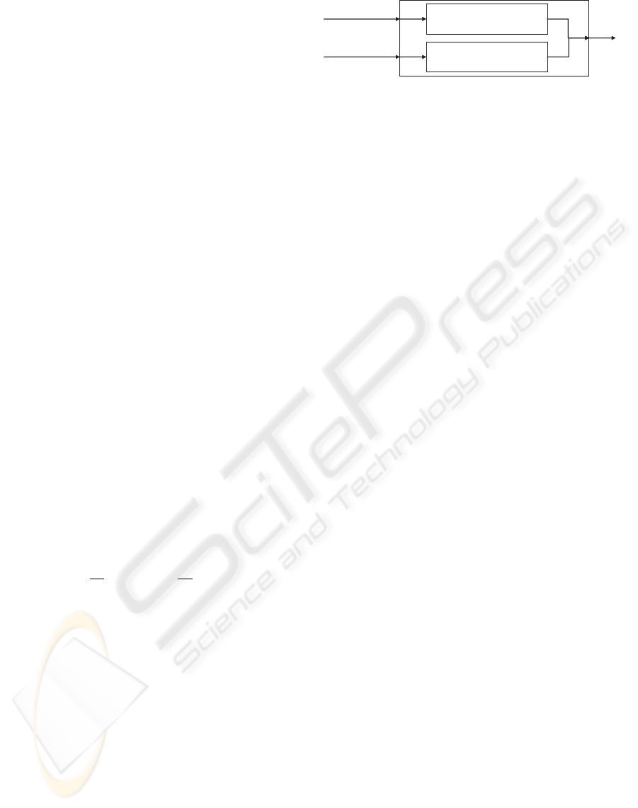
image locations, we can determine the 3D location
(ˆα
ms
k
,
ˆ
β
ms
k
,
ˆ
λ
ms
k
) by back-projection (8).
The outline of the particle filter algorithm for color-
based stereo target tracking is presented in Figure 3.
3.5 Target model update
Let
ˆ
p
l
and
ˆ
p
r
denote the estimates of the centers of
the target regions in the left and right image, respec-
tively. If the sum of likelihoods (14) of
ˆ
p
l
and
ˆ
p
r
are
higher than a threshold, it means that there is no out-
lier or occlusion at the estimated target position in the
image. Therefore, we can update the target model to
cope with illumination variations resulting in appear-
ance changes. The target models, q
l
(u) and q
r
(u), are
updated as in (Nummiaro et al., 2003):
q
l
(u) = (1 − a)q
l
(u) + ah
ˆ
R
l
(u), (20)
q
r
(u) = (1 − a)q
r
(u) + ah
ˆ
R
r
(u), (21)
where u = 1, ..., B,
ˆ
R
l
= R(
ˆ
p
l
, ˆs),
ˆ
R
r
= R(
ˆ
p
r
, ˆs),
ˆs is the scale estimate, and a ∈ (0, 1) is a factor
weighting the color model of the target at the esti-
mated positions
ˆ
p
r
and
ˆ
p
l
. This evokes a forgetting
process whereby the contribution of a specific frame
decreases exponentially in time.
3.6 Camera control
The control scheme refers here only to the pan (az-
imuth) angle α. The control of the tilt (elevation)
angle β can be done in the same manner. We use
a discrete Proportional-Integral-Derivative (PID) con-
troller given by
u
p
k
= K
p
e
k
+ K
i
T
s
T
i
k
X
i=0
e
i
+ K
d
T
d
T
s
(e
k
− e
k−1
) + u
p
0
where e
k
is the estimate of the azimuth angle at time
k as delivered by the particle filter, e
k
= ˆα
k
. The
parameters K
p
, K
i
, K
d
, T
i
, T
d
are design constants
and T
s
is the sampling period.
4 ROBOT NAVIGATION
Two behavior-based architectures for robot naviga-
tion are presented here. The general idea behind
behavior-based approaches is to decompose a task in
simpler tasks that are easier to implement and test.
The challenge of this approach remains in how to
combine these different subtasks such that the global
task is executed in a robust manner. The robot naviga-
tion problem can be subdivided into two main parts:
• How to reach the goal location?
Goal (Person)
Following Behavior
Obstacle Avoidance
Behavior
Exteroceptive
sensors
3D Goal Position
v, ω
Figure 4: Fuzzy-logic behavior based navigation controller
• How to avoid obstacles?
The presented solutions preserve this ambivalent
structure by providing a behavior-based navigation
strategy where two main behaviors process each one
of the questions raised above.
The robot navigation module produces as output a
heading direction for the robot and a speed setpoint,
usable on any mobile robotic platform. The speed set-
point depends directly on the distance to the target
person: if the robot is far away, it needs to accelerate
in order not to loose the person; when it approaches
the target, it must move with more caution to not hurt
the human. When the robot comes within one me-
ter of the target person, it will stop automatically, for
security reasons.
4.1 Fuzzy-logic behavior based
navigation controller
In this setup, depicted in Figure 4, each of the be-
haviors consists of a fuzzy logic controller relating
the input commands, i.e. the sensory data, to output
commands for the robot actuators. For the person-
following or goal-seeking behavior, the input comes
from the active stereo vision system, delivering the
3D position of the target person, whereas the obstacle
avoidance behavior uses exteroceptive sensor data to
find a path without colliding with obstacles.
4.2 Hybrid behavior based
navigation controller
We also exploit a hybrid architecture used for moving
in human-centered environments (Nuttin et al., 2003).
This architecture consists of a deliberative and a re-
active part. In this way, the advantages of both ap-
proaches are combined. The robot is able to reason
about how to reach a certain goal position, taking a
priori knowledge about the environment into account
if this is available. At the same time, it is able to re-
act very quickly to unmodeled obstacles in the envi-
ronment, by adopting a more direct coupling between
sensors and actuators. A multi-agent framework in
which behaviors can be specified conveniently was
developed for this goal, as in (Waarsing et al., 2003).
Figure 5 depicts the proposed architecture. The
navigation module as a whole calculates the linear
ACTIVE STEREO VISION-BASED MOBILE ROBOT NAVIGATION FOR PERSON TRACKING
37
Planner
Behavioral
execution
Robot Position
Odometry
Exteroceptive
sensors
3D Goal Position
∆x, ∆y, ∆θ
v, ω
Figure 5: Hybrid behavior based navigation controller
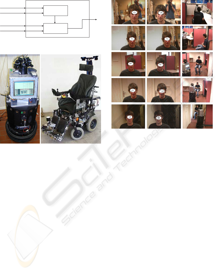
Figure 6: The Nomad200 and wheelchair with the active
stereo vision system
velocity and heading direction v and ω of the robot,
given the current robot location (x, y, θ) and its un-
certainty, the robot’s global goal given by the active
vision module, the measured ranges from the exte-
roceptive sensors, and the odometry values. During
navigation, a global planner and a behavioral execu-
tion unit co-operate.
5 RESULTS AND DISCUSSION
The overall control strategy was tested on a No-
mad200 robot, which is a pure laboratorial robot used
for testing purposes. As such, the experimental results
which are shown in this section, are obtained with
this robot. For more real-world applications, we make
use of a mobile wheelchair platform. Both mobile ro-
bot platforms are shown in Fig. 6. For this research
project, we developed a totally independent stereo vi-
sion platform consisting of a PC, with a small LCD
screen. On top of the platform, a Biclops stereo head
is installed, carrying two high-resolution Pulnix color
cameras. The whole system is totally self sustainable
as it runs on its own power resources (six 10Ah bat-
Figure 7: Target tracking results: the white ellipse indicates
the goal which is tracked, the small circles represent the
different particles of the particle filter. The columns show
(1,2) stereo head tracking, (3) robot advancing to the target.
teries). The stereo vision platform can be seen on top
of the Nomad robot in Figure 6, while a model of the
stereo vision subsystem is shown in Figure 1.
The results of the person following application are
illustrated in Figure 7. With a number of N = 70 par-
ticles and B = 8 × 8 × 8, the system is able to run in
real-time. As can be noticed, the tracker succeeds to
aim the stereo head towards the target person, with-
standing illumination changes and even though the
movement of this person was not easily predictable.
The robot navigates towards this person while avoid-
ing the obstacles on its way to come to a stop 2 meters
in front of the person.
To assess the ASVM’s performance as to the target
range estimation, we conducted an experiment where
a colored object is rotated with constant angular speed
in a plan parallel with the ground and at a height cor-
responding to that of the stereo head. In this case, the
range varies in a sinusoidal manner (see Figure 8). At
the beginning, there is a short stationary period nec-
essary for the ASVM to center the target in its field
of view. Note that the target range is tracked quite
accurately, with a small lag.
ICINCO 2005 - ROBOTICS AND AUTOMATION
38
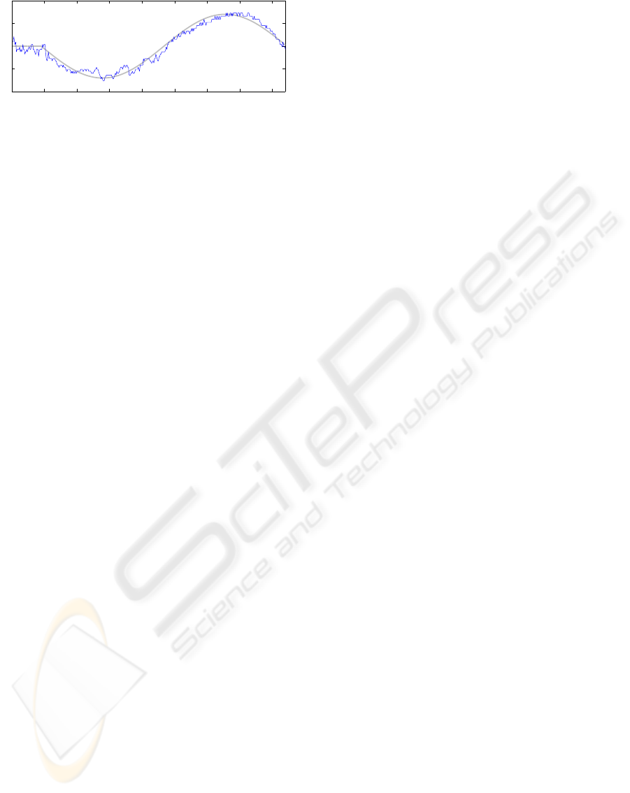
0 50 100 150 200 250 300 350 400
1.6
1.8
2
2.2
time step
distance [m]
Figure 8: Estimated target range (blue line) vs. ground truth
(gray line).
6 CONCLUSION
We have presented the active stereo vision (ASVM)
and navigation (NM) modules of a mobile robot sys-
tem designed for person following. The ASVM con-
trols a stereo head for tracking a target by means of a
color-based particle filter, robust to illumination vari-
ations, erratic target motions, and short occlusions.
To enforce the stereo constraint (the target regions
in the stereo images are correlated through the stereo
head-target 3D geometry), the measurement process
is formulated in the image plane, whereas the system
dynamics is based on the 3D position of the target.
Keeping the target in the ASVM’s field of view is
achieved by adjusting the pose of the stereo head via
a PID pan/tilt controller. Further, the estimate of the
3D target position is fed to the NM, which consists
of a behavior-based navigation controller. Two dif-
ferent navigation controllers were presented. Finally,
the concept was demonstrated by implementing it on
both a Nomad200 and a wheelchair platform.
ACKNOWLEDGMENT
This research has been conducted within the frame-
work of the Inter-Universitary Attraction-Poles pro-
gram number IAP 5/06 Advanced Mechatronic Sys-
tems, funded by the Belgian Federal Office for Scien-
tific, Technical and Cultural Affairs.
REFERENCES
Arsenio, A. M. and Banks, J. L. (1999). People detection
and tracking by a humanoid robot. Technical report,
MIT.
Arulampalam, S., Maskell, S., Gordon, N., and Clapp, T.
(2002). A tutorial on particle filters for on-line non-
linear/non-Gaussian Bayesian tracking. IEEE Trans-
actions of Signal Processing, 50(2):174–188.
Beardsley, P., Reid, I., Zisserman, A., and Murray, D.
(1995). Active visual navigation using non-metric
structure. In 5th International Conference on Com-
puter Vision, pages 58–64, Cambridge, MA, USA.
Comaniciu, D., Ramesh, V., and Meer, P. (2003). Kernel-
based object tracking. IEEE Transactions on Pattern
Analysis and Machine Intelligence, 25:564–577.
Davison, A. and Murray, D. (1998). Mobile robot local-
ization using active vision. In 5th European Confer-
ence on Computer Vision, volume 2, pages 809–825,
Freiburg, Germany.
Franz, M.-O. and H.-A., M. (2000). Biomimetic robot nav-
igation. Robotics and Autonomous Systems, 30:133–
153.
Ghita, O. and P.-F., W. (2003). Real time 3d estimation us-
ing depth from defocus. Vision, MVA (SME), 16(3):1–
6.
Koren, Y. and Borenstein, J. (1991). Potential field methods
and their inherent limitations for mobile robot naviga-
tion. In IEEE Conference on Robotics and Automa-
tion, pages 1398–1404, Sacramento, California.
Kuniyoshi, Y. and Rougeaux, S. (1999). A humanoid vision
system for interactive robots. In 1st Asian Symposium
on Industrial Automation and Robotics, pages 13–21.
Nummiaro, K., Koller-Meier, E., and Gool, L. V. (2003). An
adaptive color-based particle filter. Image and Vision
Computing, 21:99–110.
Nuttin, M., Vanhooydonck, D., Demeester, E., Brus-
sel, H. V., Buijsse, K., Desimpelaere, L., Ramon,
P., and Verschelden, T. (2003). A robotic assis-
tant for ambient intelligent meeting rooms. In 1st
European Symposium on Ambient Intelligence (EU-
SAI), pages 304–317, Veldhoven, The Netherlands.
http://www.mech.kuleuven.be/pma/research/mlr.
Perez, P., Hue, C., Vermaak, J., and Gangnet, M. (2002).
Color-based probabilistic tracking. In European Conf.
Computer Vision (ECCV), volume 1, pages 661–675.
P
´
erez, P., Vermaak, J., and Blake, A. (2004). Data fusion for
visual tracking with particles. Proc. IEEE, 92:495–
513.
Ping, H., Sahli, H., Colon, E., and Baudoin, Y. (2001). Vi-
sual servoing for robot navigation. In 3rd Interna-
tional Conference on Climbing and Walking Robots:
Clawar 2001, pages 255–264, Karlsruhe, Germany.
Schlegel, C., Illmann, J., Jaberg, H., Schuster, M., and
Worz, R. (2000). Integrating vision based behaviors
with an autonomous robot. Videre: Journal of Com-
puter Vision Research, 1(4):32–60.
Strens, M.-J.-A. and Gregory, I.-N. (2003). Tracking
in cluttered images. Image Vision and Computing,
21(10):891–911.
Vieville, T. (1997). A few steps towards 3D active vision.
Springer, Berlin.
Waarsing, B., Nuttin, M., and Brussel, H. V. (2003). A
software framework for control of multi-sensor, multi-
actuator systems. In International Conference on Ad-
vanced Robotics (ICAR), Coimbra, Portugal.
Wilhelm, T., Bohme, H.-J., and Gross, H.-M. (2004). A
multi-modal system for tracking and analyzing faces
on a mobile robot. Robotics and Autonomous Systems,
48:31–40.
ACTIVE STEREO VISION-BASED MOBILE ROBOT NAVIGATION FOR PERSON TRACKING
39
