
DESIGN AND DEVELOPMENT OF AUTOMATED SYSTEM FOR
LOCALISED ELF MAGNETIC FIELD STIMULATION OF THE
HUMAN BRAIN
Dean Cvetkovic and Irena Cosic
Australian Centre for Radiofrequency Bioeffects Research (ACRBR)
RMIT University, School of Electrical and Computer Engineering
GPO Box 2476V Melbourne VIC 3001 Australia
Keywords: ELF, EMF, Bioeffects, Brain, EEG, Robotic Arm, Stepper Motors, Bluetooth.
Abstract: The automated system was designed and developed for accurate and fast localisation of extremely low
frequency (ELF) electromagnetic field (EMF) exposure to any particular brain region and therefore record
for any changes in the EEG activity before and after stimulation. The automated system consisted of a
general user interface (GUI) where the users had the ability to precisely control and move an EMF source
(coil) via robotic arm to any EEG electrode position or region. The 3-D movements of the robotic arm were
controlled via a serial linked motor driver board that controlled two motors. The software was able to
initially store the estimated 3-D EEG electrode positions and therefore identify the areas where ELF EMF
exposure from the coil could be applied. The testing and final measurements of this system revealed the
robotic arm precision of 0.1mm and maximum speed of 0.211 cm/sec (x-axis) and 0.827 cm/sec (y-axis).
1 INTRODUCTION
A particular system needed to be designed with the
purpose to modernise bioelectromagnetic apparatus
and aid researchers in unravelling many of the
unknown changes in EEG activity due to ELF/RF
EMF exposures. Accurate and fast automated system
needed to be designed and developed to provide an
Extremely Low Frequency (ELF) Electromagnetic
Field (EMF) exposure at any specific 3-D positions
or region around the human head. Once the EMF
source (coil) could be positioned and exposure
applied to subject’s head, the resultant electrical
brain activity (EEG) could be recorded. The EEG
recording and ELF EMF exposure were not to be
applied simultaneously due to EMF interference and
induction of electrical fields within the EEG leads
and electrodes, resulting in inaccurate recorded EEG
signals.
1.1 Background
It has been known that the brain cells send electrical
signals along the fibres that make up their
communication networks. Considering that changing
(sinusoidal) magnetic fields can induce current in
electrical conductors, researchers thought that a
magnetic pulse might stimulate currents in the brain
and therefore alter the brain’s electrical activity
(EEG) (Nature, 2002). Researchers have used a
Transcranial Magnetic Stimulation (TMS) technique
in the past and have reported that depending on the
intensity, frequency and localisation of the magnetic
field applied to brain, the simple cognitive tasks
could be explained (Walsh V., 1999)(Ueno S.,
1999).
One study investigated whether an alternating
3Hz magnetic field of 0.1mT applied to the head
over a period of 20 minutes caused any changes in
EEG parameters. This study was able to justify that
alternating weak magnetic fields do affect the
specific EEG activity (Hausser K, 1997). It has also
been reported that magnetic field stimulation
localised in the region of the “Hess” area of cat’s
brain can cause an impulse and a proliferation of
reactions from neural cells, which as a result triggers
the sleep centre and causes it to resonate in
316
Cvetkovic D. and Cosic I. (2005).
DESIGN AND DEVELOPMENT OF AUTOMATED SYSTEM FOR LOCALISED ELF MAGNETIC FIELD STIMULATION OF THE HUMAN BRAIN.
In Proceedings of the Second International Conference on Informatics in Control, Automation and Robotics - Robotics and Automation, pages 316-321
DOI: 10.5220/0001186703160321
Copyright
c
SciTePress

synchronisation (Hu Y., 1998). A simulated brain
wave pattern of slow wave sleep was coupled from
the coil to cat’s brain, in order to induce the
encephalic electrical activity to synchronise
gradually with the external low-frequency magnetic
fields and thus induce sleep in the cat.
An interesting study, led by Cook and Persinger,
conducted an investigation to find any interaction
with and to control the EM correlates of
consciousness generated by the brain through
applied complex magnetic fields whose
characteristics simulated natural, transcerebral EMFs
(Cook C. 1999). They designed a device to produce
rotational, circumcerebral transient magnetic fields
between 5 and 10µT, using 8 solenoids, which were
arranged circumcerebrally (every 45°) at the level of
the temporal-orbital plane. There were two
conditions utilised for this experiment: clockwise or
counter-clockwise arrangement of the 8 solenoids.
For the clockwise condition, solenoid 1 was placed
over the right prefrontal region such that solenoids
1-4 were equally spaced (45°) over the right
hemisphere and solenoids 5-8 were equally spaced
over the left hemisphere, along the orbito-temporal
plane. For the counter-clockwise condition, solenoid
1 was placed over the left prefrontal region such that
solenoids 1-4 were placed over the left hemisphere
and solenoids 5-8 were placed over the right
hemisphere. The counter-clockwise arrangement
generated a field sequence that moved in a rostral to
caudal direction along the left hemisphere but in a
caudal to rostral direction along the right
hemisphere. The frequency characteristics employed
burst-firing and frequency modulated “Thomas
pattern” (Thomas A.W, 1997).
They concluded that during the counter-clockwise
rotations, the conscious awareness, as inferred by
perception of time intervals, involved a process that
may be recreated approximately every 20-25ms and
may be affected by the right hemispheric activity.
The design of the rotational eight solenoid system
with pulsed magnetic fields has led to undertake
design and develop an automated system that would
localise a single solenoid to any head region (EEG
electrode position) and apply a sinusoidal magnetic
field to it in order to investigate any changes in EEG
activity.
2 DESIGN PROCESS
In the project, there has been several functional
system attributes mentioned that the system should
and may include:
• Self calibration and alignment properties.
• Scan the X and Y coordinates of the robotic arm
and record these points as origin reference.
• Ability to keep a record of all coordinates and
10-20 International EEG Electrode Placement
Scheme points for each test subject.
• Capability to analyse the information in
conjunction with measured EEG readings at
specific testing intervals.
• Utilise Bluetooth module to send and receive
data to and from PC’s microcontroller board.
There have been many different processes used in
order to complete the design and development of
this system. The design processes have therefore
been divided into three major parts: Mechanical,
Software, and Hardware processes.
2.1 Mechanical Design Process
For the mechanical design process of the robotic
arm, important structure design factors needed to be
taken into account, such as precise component
dimensions; minimisation of friction due to movable
plate movements; light-weightiness; durability; and
material of non-electromagnetic properties. In order
to minimise any induced currents onto EMF
exposure system, and maintain stable EMF level
during the experiment, a non-electromagnetic
material such as acrylic was selected.
2.2 Software Design Process
The Control Software design process was
undertaken throughout 9 versions to test and
improve acceptable software modules and reject
unsatisfactory modules. There have been six
software modules developed: Table, Move, Head,
Web, Auto-calibrate, Settings and Communication
Module.
At the initial stage of software design process,
only Table, Move and Head modules were
undertaken. The other modules were completed in
the final design process stage. The main goal of the
‘Table Module’ (TM) was to display reference
positions for sets of points located on the head that
the arm must move to. The main function of this
module was to save a current reference position of
the arm to one set of points in the table and also to
DESIGN AND DEVELOPMENT OF AUTOMATED SYSTEM FOR LOCALISED ELF MAGNETIC FIELD
STIMULATION OF THE HUMAN BRAIN
317
update the selected point in the ‘Move Module’
(MM) to provide quick access to saved points. The
initial version of the TM only contained the data
table. At this stage only the main modules had been
created to visualise the software design. The second
version of the TM has been linked with the other
modules so that points could be saved in the table.
There was little more development to the TM until
version 6 where a large number of modules had been
altered. As a result the TM inherited a button from a
now obsolete module. This button allowed the TM
to record the current arm reference for the selected
point or to clear the selected point. The final version
of the TM has not visually changed much since
version 6. There has been a global option
implemented to change the display of the reference
points from Stepper motor positions to Degree
positions, which changed the way the module
displayed the saved points. There was also a
function implemented to save the points to an output
file, which can then be reloaded.
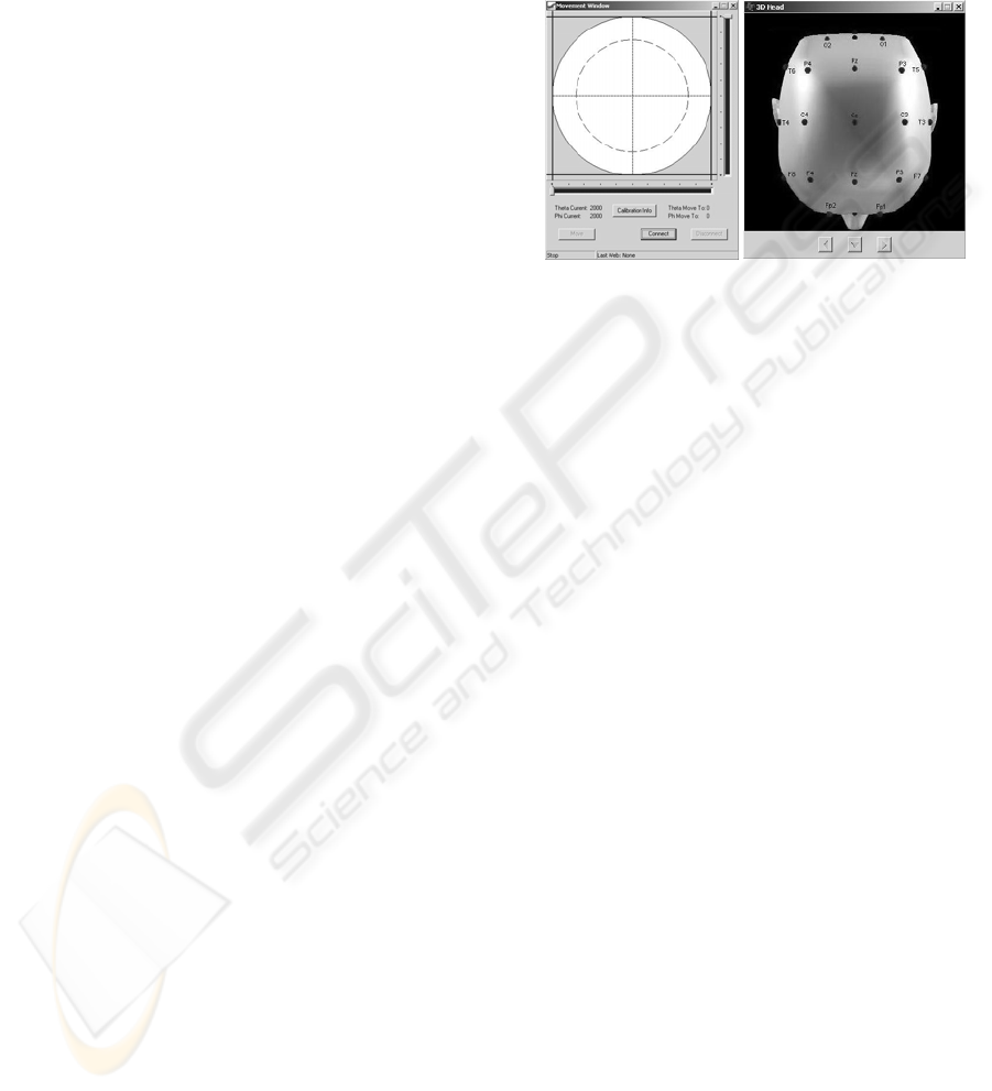
2D ‘Head Module’ (HM) has been provided as a
visual reference to select a set of points. A point
could be selected by clicking on any of the red dots
displayed in the image, which will update the current
selected point in the TM, as shown in Figure 1. The
first version of the HM was simply a plain 2D head
with marked X’s in the estimated point positions.
The final 3D HM has a three-dimensional view of
the head from multiple angles, which could allow
the user to focus on any required area of the head.
3D HM in version 6 was created from an AutoCAD
program of a head geometry that had been scanned
and measured to produce an accurate representation.
From this program, multiple jpeg images were
created of the head at different angles. The 3 buttons
at the bottom controlled the rotation of the head and
each labelled point was selectable.
‘Move Module’ (MM) was responsible for
sending the control signals, which moved the arm.
The final version of the MM provided 3 different
methods for scrolling to a point. The first method
was the fastest by a point and click on the head
diagram. The next method was to move the slider
bars on the left and the right of the head diagram.
These were useful if only movement in one axis was
required. The final method was the most accurate
and was useful for fine-tuning the arm position. It
was performed by pressing the arrow keys, the left
and right arrow keys move along the ‘Theta’ axis
and the up and down arrow keys move along the
‘Phi’ axis. The MM has been the most complex to
design, since it was the module responsible for
sending the control signals. The first version of the
move module contained only basic commands.
There was a select point option to select a previously
referenced point and a move button to go to the
selected point and some labels to indicate the current
position of the arm while it’s moving. Since the
control signal framework has not been established at
this point, it was difficult to determine the module
requirements.
Figure 1: Move and Head Modules
By version 6 the control signal framework was ready
to be defined and by the final version, the additional
features such as Connect/Disconnect and the
Movement Control options were introduced. The
Connect/Disconnect was used to secure a COM port
for communication to the PIC controller. The
Movement Control buttons moved the arm for the
initial calibration. Rather than use buttons to move
on an axis, slider bars and the original head model
from version 1 were used to visually select a point.
In the final version a button has been added to show
the maximum step readings sent by the PIC after a
full calibration has been performed. This also
allowed the software to request a full or a quick
calibration, as shown in Figure 1.
2.3 Hardware Design Process
The scope of the system hardware was centred on a
PIC18F6720 microcontroller, which was responsible
for moving the robotic arm and communicating with
the GUI. Firmware prototyping was done on a
PIC18F8720 EVB. Microchip MPLAB 6.63 was
used with the MC18C compiler for fast firmware
development and advanced debugging with the use
of the Microchip In Circuit Debugger (ICD 2) tool.
The following firmware modules were prototyped
on the EVB:
• RS232 communication structures / modules
• Interrupt driven Shaft encoder module.
• Stepper Motor control module.
• Most system algorithms, including the arm
movement and RS232 packet constructor and de-
constructor algorithms.
ICINCO 2005 - ROBOTICS AND AUTOMATION
318
Schematic and PCB design was done in Portal DXP
where many advanced features of the software
package were used to minimize error in the final
design. Due to the small track size and complexity
of the final PCB artwork and advanced PCB etching
process was used. Placement and soldering of the
surface mount
3 FINAL DESIGN SYSTEM
The final design system was once again divided into
three major parts: Mechanical, Software and
Hardware Design.
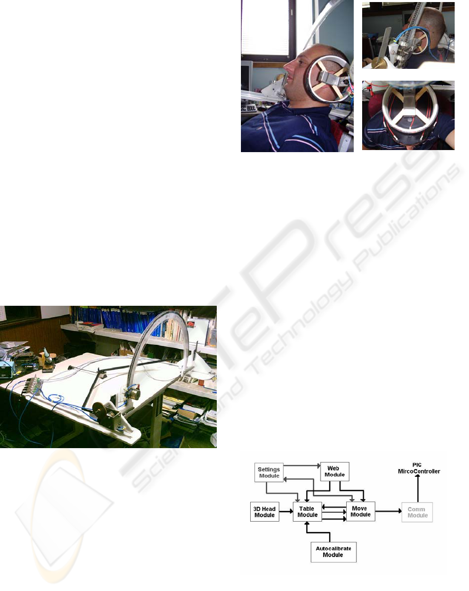
3.1 Mechanical Design
From the 1
st
design to the final design, the robotic
arm had undergone significant changes. Figure 2
below shows the final design of the robotic arm. It
was made up of a main frame (an arc), which could
rotate on its middle axis and a plate attached to it, to
move along the arc. The most vital factor was the
ability to rotate the robotic arm on its middle axis as
well as moving the plate to its full extent.
Figure 2: Move and Head Modules
In the initial design, a normal 180
o
arc was
designed to move the plate around. The U-shaped
corners allowed the plate to move to its full extent,
while the side of the U-shape corners could support
the full weight of the robotic arm. To hold the EMF
source (coil), a plate with a stepper motor attached
to it was designed. The plate has a holder
constructed of lightweight and strong aluminium,
consisting of non-magnetic properties. The stepper
motor was attached to a cog, which rotated and
moved the whole plate up and down the mechanical
structure. A laser pointer was also attached to the
middle of the plate. Figure 3 shows the EMF coil
positioned at top and side head positions.
Figure 3: EMF Coil Positioned at Top and Side Head
Positions.
To enable the user to position the robotic arm
directly on top of subject’s head, a base was
constructed to slide forwards and backwards and be
locked to specific position. To limit the movement
of the robotic arm to 180
o
on its X & Y-axis, micro-
switches were attached to the sides. Once the arc or
plate touched a switch, the software would register
that point as the limit. This was particularly useful
for auto-calibration and ensuring that the arm did not
exceed its maximum movement.
3.2 Software Design
The Control Software was composed of 7 main
modules. Each of these performed too many
functions to mention them all, but the main functions
they perform were: select a point; save a reference to
that point; alter arm reference point (Position to
move to); and move arm to reference point.
A functional block and directional arrows diagram
is shown in Figure 4 above, indicating flow of data
or an instruction.
Figure 4: Software Functional Block Diagram
The TM held arm reference locations for the 19
electrode placement points. It also held the currently
selected point and could be instructed to change the
selected point via the user interface or the 3D HM.
DESIGN AND DEVELOPMENT OF AUTOMATED SYSTEM FOR LOCALISED ELF MAGNETIC FIELD
STIMULATION OF THE HUMAN BRAIN
319
When the selected point has been changed, it sent
the arm reference locations to the MM for display. If
an empty point has been selected and the button
“Calibrate Point” was selected, the current reference
position of the arm was saved to the selected point
and updates the table. If by any chance a point was
selected that already has a reference position saved
to it, the button changes to “Reset Calibration” and
if selected, it will delete the reference position for
that point. The only function the 3D HM provided
was to update the selected point on the TM.
The primary responsibility of the MM was to hold
the selected arm reference position to be transmitted
to the PIC Controller. The arm reference position
could be altered by selecting a point with a saved
reference position or by manipulation of the controls
in the MM. Since the ‘Communication Module’
(CM) has no direct user interface, the MM has some
extra buttons to provide that interface. The
“Connect” and “Disconnect” captured a COM port
for the software to use for communication to the
PIC. When it was connected and the “Move” button
was selected, the selected reference position of the
arm was transmitted to the PIC. The axes used to
reference the arm positions were common circular
polar axes.
A small HTTP server has been integrated into the
software. This allowed a wireless enabled PDA with
a Web Browser to transmit move instructions,
allowing the operator to precisely conduct control
commands. Using ‘Auto-calibrate Module’ (AM)
and by calibrating the points listed, the remaining
reference positions could be estimated. This saves
the operator time by only having to save 6 reference
positions instead of the entire 19 points. The
reference positions were calculated by an
approximate estimate. The Settings Module served
to fine tune settings of the other modules.
The Communication Module (CM) was
responsible for interfacing between the MM and the
serial communications port. The Windows API
functions for the serial port were used to transmit
and receive data. A communications class for
Borland Builder C++ has been used as an interface
for the Windows API. When the “Calibration Info”
button on the MM was selected, it brought up a
window containing the current calibration data. If
“Yes” was selected then a full calibration request
was sent from the CM and the calibration data was
updated. If “No” was selected then a quick
calibration request was sent from the CM and arm
moved to a known position. If the “Move” button
was selected on the MM, a move request was sent
via the CM. The final testing the CM and parts of
the MM, required knowledge of the serial output.
This was accomplished by the creation of a PIC
Emulator program, which has been set up to test all
functions of the software program.
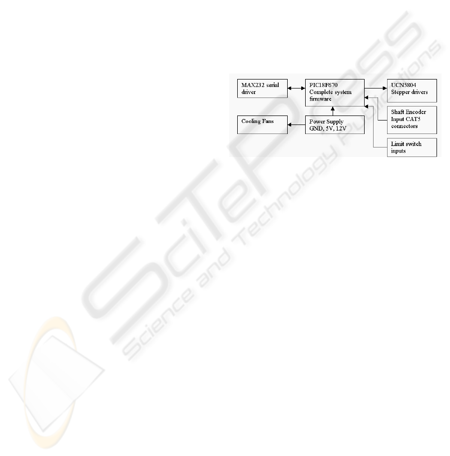
3.3 Hardware Design
The PCB was implemented with mostly surface
mount components and connectors. The hardware’s
PIC18F6720 microcontroller had an ability to move
the arm to any position, determine the current
position and direction of movement and
communicate with the GUI. Figure 5 shows the
functional block diagram of the hardware subsystem
interconnections to the micro controller.
Figure 5: Hardware Interconnections
The PIC18F6720 controller provided the
following functionality to:
• Handle both RX and TX communications with
the GUI.
• Drive the system stepper motors, via the
UCN5804 high power stepper motor drives.
• Determine current location from quadrate
output shaft encoders.
• Sense a domain limit changes on the limit
switch inputs.
• Move the arm to the required position as
instructed by the GUI.
The UCN5804 high power stepper drivers were
used to rotate the stepper motors at variables speeds
in both forward and reverse directions. There were
two UCN5804 drivers on the final design. These
drivers controlled the X and Y movements. The PCB
has prevision for a third driver to control automated
Z-axis movement if required in the future. Due to
the high power requirements of the stepper motors,
an average of 0.5A was passed though each of the
UCN5804’s, thus processor controlled cooling fans
were positioned over the drivers to avoid heating
beyond their specifications.
The PCB contained a MAX232 serial driver for
signal conditioning and data transmission. The
ICINCO 2005 - ROBOTICS AND AUTOMATION
320

MAX232 interfaced with the PIC18F6720 USART
and serial crossover was done on the PCB to make
the hardware more compatible with standard PC’s.
Communication to and from the PCB was done via
packet transmission and reception (9600 bps, 8 data
bits, parity none, stop bits 1 and no hardware flow).
The packet structure was a fixed length with an
identifier and data field. Bluetooth communications
module was attached to the RS232 DB9 connector
which then interfaced the USART module in the
PIC18F8720, enabling wireless communications
between the hardware and GUI.
4 PERFORMANCE & RESULTS
To test the hardware performance, a sequential test
procedure was constructed in a proceeding order
where the following test procedure required the
previous test to be valid. Arrays of small firmware
testing applications were written to exercises
specific components of the subsystem under test.
Once the automated system was finalised and fully
operational, particular measurements were taken to
determine the accuracy and speed of our system. It
was observed that the system had an accuracy of
0.1mm for both X and Y-axis. The speed of the X-
axis was 0.211 cm/sec and the speed of the Y-axis
was 0.827 cm/sec, as shown in Table 1.
Table 1: The Accuracy and Speed of X and Y-Axis
X-axis Y-axis
Accuracy (mm) 0.1 0.1
Speed (cm/sec) 0.211 0.827
5 CONCLUSION
The automated system was designed and developed
for accurate and fast localisation of extremely low
frequency (ELF) electromagnetic field (EMF)
exposure to any particular brain region. The
automated system consisted of mechanical, software
and hardware designs which all passed through a
development process of refinement and
improvement. The final design of the robotic arm
was constructed of a main frame (an arc), which
could rotate on its middle axis and a plate attached
to it, to move along the arc. A general user interface
(GUI) was also developed to precisely control and
move an EMF coil via robotic arm to any EEG
electrode position or region. The software was able
to initially store the estimated 3-D EEG electrode
positions. The 3-D movements of the robotic arm
were controlled via a serial linked motor driver
board that controlled two motors.
ACKNOWLEDGEMENT
The authors gratefully acknowledge the NHMRC for
their support of the ACRBR which has assisted this
work.
REFERENCES
Magnetic Mind Games, 2002, Nature, 417, pp.114-116.
Ueno S., 1999, Biomagnetic Approaches to Studying the
Brain, IEEE Engineering in Medicine and Biology, pp.
108-120.
Walsh V. and Rushworth M., 1999, A Primer of Magnetic
Stimulation as a Tool for Neuropsychology,
Neurolopsychologia, 37, pp.125-135.
Hausser K., Tellschaft D. and Thoss F., 1997, Influence of
an Alternating 3Hz Magnetic Field with an Induction
of 0.1 mT on Chosen Parameters of the Human
Occipital EEG, Neuroscience Letters, 239, pp. 57-60.
Hu Y., Feng Y.M., Wang MS., Lu WW., 1998, The Effect
of Magnetic Stimulation on Potential Rhythm of
Cerebral Cortex, IEEE Engineering in Medicine and
Biology Society, 20(6), pp. 3288-3289.
Cook C. M., Koren S. A. and Persinger M. A., 1999,
Subjective Time Estimation by Humans is Increased
by Counter-clockwise but not Clockwise
Circumcerebral rotations of Phase-Shifting Magnetic
Pulses in the Horizontal Plane, Neuroscience Letters,
268, pp. 61-64.
Thomas A.W., Kavaliers M., Prato F.S. and Ossenkopp
K.P., 1997, Antinociceptive Effects of Pulsed
Magnetic Fields in the Land Snail: Cepaea Nemoralis,
Neuroscience Letters, 222, pp. 107-110.
DESIGN AND DEVELOPMENT OF AUTOMATED SYSTEM FOR LOCALISED ELF MAGNETIC FIELD
STIMULATION OF THE HUMAN BRAIN
321
