
SELF-LEARNING DISTURBANCE COMPENSATION FOR ACTIVE
SUSPENSION SYSTEMS
Eckehard M
¨
unch, Henner V
¨
ocking, Thorsten Hestermeyer
University of Paderborn
Pohlweg 98, D - 33098 Paderborn
Keywords:
mechatronics, learning, distributed optimization, active suspension, railway systems.
Abstract:
Ride comfort and safety of vehicles can be increased by active suspension systems. A problem is the detection
of disturbances which can generally not be measured until they impact the chassis. Provided guidance and
disturbance are known in advance, a controller can use this information to achieve considerably improved
behavior. This paper presents an approach in which railway vehicles coupled in a network, in repeated runs
over the same track section, learn a disturbance compensation that can almost entirely compensate for sta-
tionary disturbances, i.e., disturbances that occur at the same spot in equal measure. Here information on the
respective track section is sampled, stored locally at the track, and retrieved by the succeeding vehicle which
will use them for an improved compensation for the occurring disturbances and again store information there.
This iterative procedure results in an optimal compensation.
The algorithm is described and criteria for its design are derived from digital control theory. The procedure was
implemented on a testbed for a semi-vehicle with three degrees of freedom. The results of the measurements
are displayed and evaluated in this paper.
1 INTRODUCTION
Today, active suspension systems are well established
in theory and practice. This holds especially true for
automotive applications. When looking at the railway
industry, vehicles with active suspension are avail-
able, but these systems usually focus on tilt and cen-
tering of the coach body rather than on ride comfort.
However - even if rare - , there has also been some
work on active damping in industry (Streiter et al.,
2001) and public research. This work uses as applica-
tion example the system setup of the railway system
”Neue Bahntechnik Paderborn”, which is explained
in more detail in section 2.
Most of the vast number of literature on the control
of active suspension systems focuses on single vehi-
cles. Collaborative vehicle networks, however, offer
a promising way to improve ride comfort even fur-
ther: This paper shows, that it is possible to reduce
the body motion by a great extent by using the expe-
rience gained by other vehicles. In order to do so, two
things are necessary: First, an algorithm is required,
that determines information about the track excitation
and uses this in the control algorithm of the active sus-
pension. Second, a collaborative network with com-
munication infrastructure has to be set up. This paper
focuses on the first step.
The paper is structured as follows:
Section 2 presents the basic idea for the overall sys-
tem setup in the collaborative vehicle network. With
this setup in mind, section 3 describes an example
suspension system and the control structure including
a learning algorithm. Section 4 develops this learning
algorithm. In order to show the applicability of the al-
gorithm and its benefits, the system was implemented
on a suspension test rick described in section 5. Sec-
tion 6 discusses the results. The paper concludes with
an outlook in section 7.
2 PREVIEW SYSTEMS FOR
ACTIVE SUSPENSIONS
When designing an active suspension it is important
to put special care on the employed sensor concept
and the control strategy as both play a mayor role
in the success of the system. One important aspect
became clear already with first realizations of active
suspension systems: Disturbance compensation using
32
Münch E., Vöcking H. and Hestermeyer T. (2005).
SELF-LEARNING DISTURBANCE COMPENSATION FOR ACTIVE SUSPENSION SYSTEMS.
In Proceedings of the Second International Conference on Informatics in Control, Automation and Robotics, pages 32-38
DOI: 10.5220/0001185700320038
Copyright
c
SciTePress
information about the ground excitation can improve
the ride comfort considerably. (J
¨
aker, 1990) e.g. used
a disturbance compensator as part of the control law
for the active suspension in an off-road truck with
great success
1
.
The way in which the ground excitation is deter-
mined has significant influence on the compensation
result. Due to actuator dynamics it is vital to know
the ground excitation as early as possible. In the
optimal case the excitation is known before it actually
hits a wheel. This is known as ”preview”. Preview
information for the rear wheels can be gained by
using information from the front wheels (so called
”internal preview”). This is quite a convenient way
for disturbance compensation in trains, where the
locomotive can collect track information and transfer
it to the carriages. In short vehicles like cars however,
the influence of the front wheels on comfort is
very high and internal preview provides only small
benefit (Rutz, 1987). Preview information for the
front wheels would therefore help to improve ride
comfort even more. Unfortunately, looking at a single
vehicle, collecting preview information for the front
wheels is an arduous and costly business.
2
A much
simpler way to obtain the desired information can be
found for vehicles integrated in a network. (Ioannou,
1998) proposes such an infrastructure supported
network for highway vehicles. This paper focuses on
the railway system ”Neue Bahntechnik Paderborn”
(NBP) (Hestermeyer, 2003), which supplies a perfect
infrastructure for the new preview system presented
here:
The railway system NBP features small au-
tonomous railway vehicles of van size with a fully-
active suspension system. The shuttles are propelled
by a double- fed asynchronous linear motor. For the
implementation of the motor, the track is divided into
sectors, which are equipped with their own computer
hardware. The creation of the propelling forces re-
quires fast communication between the shuttles and
the track. Fig. 1 shows the information and commu-
nication structure of the NBP-system (Zanella et al.,
2002). The available computation power and commu-
nication infrastructure can be used to set up a preview
system for the active suspension (Hestermeyer et al.,
2004; M
¨
unch et al., 2004).
The system structure shown in Fig. 1 suggests the
following set-up for the determination of the track
excitation:
1
Information about the wheel excitation was derived
from an observer based on signals from accelerometers
mounted on the axles.
2
(Donahue, 2001) e.g. describes a military external pre-
view system with expensive radar and optical sensors.
Track
ControlCenter
FC FC FC FC FC FC FC FC
SectorControl SectorControl
MainControlCenter
Communication
SectorControl
FrequencyConverter
&LocalControl
Figure 1: Communication structure for the railway-system
”Neue Bahntechnik Paderborn” (Zanella et al., 2002)
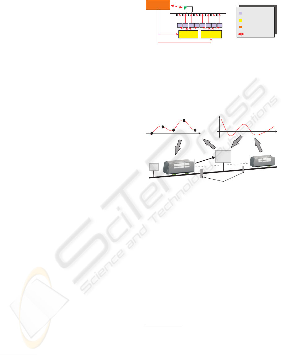
In a first step, the track is logically devided into
different sections and an agent network is allocated to
the track. One track agent is allocated to each section
(Fig. 2).
3
track
agent
excitationtrajectories
comfortmeasurement
x
x
e
r
e
q
u
e
s
t
incoming
shuttle
outgoing
shuttle
sectionboundaries
Figure 2: Determination of preview information by multi-
agent optimization
When a shuttle wants to enter a special section, it
contacts the track agent and receives in return an es-
timation of the track excitation it can use for distur-
bance compensation
4
After completing the section the
shuttle answers with a performance rating, which is
used by the track agent to optimize the trajectory. In
case of a communication error, disturbance compen-
sation is simply turned off. This results in less com-
fort but is otherwise uncritical.
Next to the benefit of improving ride comfort by
optimal disturbance compensation, this method of-
fers an excellent way of monitoring the track quality,
as the track information is continously updated with
each shuttle. Special measurement runs can be re-
duced or maybe even totally stopped.
3
Comparing Fig. 1 and 2 it seems obvious to select the
sections according to the motor sectors and download the
track agent software on the available sector hardware. How-
ever, this is not a prerequisite. The multi-agent software can
also be run on centralised hardware.
4
The dynamics of the respective shuttle has to be con-
sidered when using the preview information. Otherwise the
optimization of the preview information in the track agent
might yet converge, but is now valid only for shuttles with
similar dynamics.
SELF-LEARNING DISTURBANCE COMPENSATION FOR ACTIVE SUSPENSION SYSTEMS
33
3 ACTIVE SUSPENSION
CONTROL
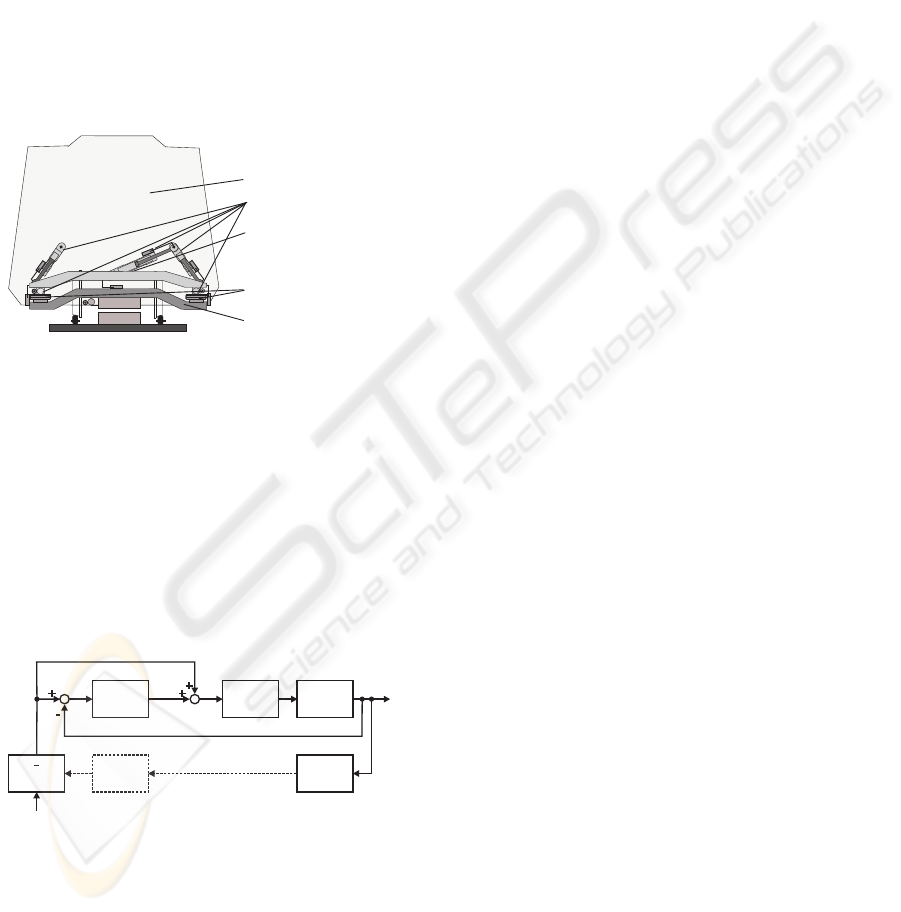
Suspension System Before discussing the en-
visioned control system in more detail, it is first
necessary to have a look at the physics of the re-
garded active suspension system (fig 3): Car body
and bogie are connected by air springs. The function
of passive dampers is taken on by an active system
of hydraulic cylinders that creates damping forces by
displacing the spring bases. The displacement vector
x
disp
yields the necessary cylinder displacements
l
cyl,i
by computing the inverse kinematics of the
cylinder arrangement.
undercarriage
suspensionframe
carbody
suspensioncylinder
airspring
Figure 3: Structure of active suspension
Control Structure As already mentioned in the in-
troduction, this paper focuses on the realization of
the disturbance compensation and the trajectory opti-
mization of the distributed control system envisioned
in section 2. Communication issues and questions
arising from the multi-agent implementation are dis-
regarded. Fig. 4 shows the structure of the self-
learning control system including the learning algo-
rithm.
+
+
controller
inverse
kinematics
plant
learning
algorithm
+
-
f
s
f
i
objective
generation
obj
x
active
x
disp
l
cyl
y
f
Figure 4: Structure of learning algorithm
The basis of the active suspension control is a sim-
ple feedback law (block ”controller”) assuring suffi-
cient damping of the car body. The control law uses
the relative position y between body and bogie to
compute the necessary displacement x
active
.
In order to minimize the absolute movement of the car
body, an additional relative displacement signal f is
introduced, which includes reference and disturbance
information in dependance of the shuttle position s
(Hestermeyer et al., 2004). The table
¯
f = (s
i
, f
i
) de-
termines f from s by interpolation.
Based on the system response,evaluated by the block
objective generation, a superposed learning algorithm
computes a trajectory that reduces the influence of
disturbances in the track by adding the signal f to the
relative displacement between body and bogie.
Section 2 suggested the usage of the track exci-
tation as disturbance compensation. This requires
knowledge of vehicle and actuator dynamics when
using the excitation trajectory in the controller. In a
first step, this dynamics was not explicitly considered
in this paper, so that car body and actuator dynamics
were reflected in the determined trajectories.
4 LEARNING ALGORITHM
During the run over a track section different distur-
bances affect the chassis of a shuttle. These dis-
turbances can be distinguished into stochastic distur-
bances and stationary disturbances, which recur at the
same place of the track section. The learning algo-
rithm presented here identifies and compensates these
stationary disturbances on the chassis. The objective
here is to keep the car body of the shuttle as still as
possible, in order to improve the comfort of passen-
gers.
As described in section 3 the learning algorithm de-
termines a trajectory as a sequence of numbers f
k
i
. k
indicates the step number of the learning process and
thus the number of shuttles that have crossed the sec-
tion.
The shuttle measures the movements of the car
body during the passage over the track section. After-
wards the data is given back to the learning algorithm,
which determines the new sequence f
k+1
i
.
Learning Algorithm As learning algorithm a com-
putation instruction of the form
f
k+1
i
= f
k
i
− K
a
· y
k
j
(1)
with
j = i + h (2)
was chosen. The value K
a
gives the learning factor
of the algorithm and y
k
j
the deviation of the car body
position. The value h reflects the dynamics of the car
body and indicates a shift of the f
k
i
signal compared
to the associated measuring point. This shift is cho-
sen according to the cut-off frequency of the car body
dynamics T and the travel speed of shuttle v.
ICINCO 2005 - INTELLIGENT CONTROL SYSTEMS AND OPTIMIZATION
34
For the passage over the regarded track section a
constant speed
v(t) = const. (3)
is assumed.
Convergence Analysis The learning algorithm in
equation (1) has great similarities to the description of
discrete controllers. They differ in the meaning of the
counting variable k, which describes the progressing
of the time with discrete controllers. In the learning
algorithm presented in this paper the variable k indi-
cates a new run over the respective track section.
It is obvious to analyze the convergence char-
acteristics of the learning algorithm by means of
well-established digital control-engineering methods
(Hanselmann, 1984). Therfore it is necessary to de-
scribe the shuttle-dynamics by a mathematic model.
In order to treat the supporting points independently
from each other, some simplifications must be made
for the convergence analysis of the learning algo-
rithm. For the feed-forward signal a simple step-
function in place of the interpolation function is used.
Furthermore an ideal reference reaction of the car
body is assumed. The system response of the shut-
tle can be described with the simple model
y
k
j
= K
p
·
f
k
i
+ u
k
i
(4)
in which u
i
describes the track disturbance at the sup-
porting point i.
Inserting into the learning algorithm equation (1)
yields
f
k+1
i
= f
k
i
− K
p
· K
a
·
f
k
i
+ u
k
i
(5)
The use of the Z-transformation with equation (5)
results in the transfer function:
G(z) =
f
i
(z)
u
i
(z)
=
K
p
· K
a
1 − K
p
· K
a
− z
(6)
In order to analyze the stability of the system, the
poles of (6) can be used.
z = 1 − K
p
· K
a
(7)
For a stable system behavior the pole stays within the
unit circle.
0 < K
p
· K
a
< 2 (8)
In the stability analysis presented above strong sim-
plifications were made. The dynamic behavior of
the shuttle was reduced to a simple gain factor K
p
,
whereby the dependencies between neighbored sup-
porting points were eliminated. If one selects this gain
K
p
to be the overshoot of the car body response to
a unit step, then one receives a useful estimation for
the feasible range of the learning factor K
a
. In prac-
tice the convergence will be assured by reducing the
learning factor to a relative small value. On the one
hand this leads to a decreased learning speed, on the
other hand the insensitivity of the feed-forward signal
f
k
i
to the above mentioned stochastic disturbance is
increased.
5 REALISATION
For a test in practice, the approach for a preview con-
trol presented here was realised in a simplified envi-
ronment. In the following, we will expound the con-
figuration of the testbed and present the implementa-
tion of the procedure described.
Configuration of the Testbed The control of the
damperless suspension/tilt system is described in
(Hestermeyer et al., 2003) for the complete vehicle.
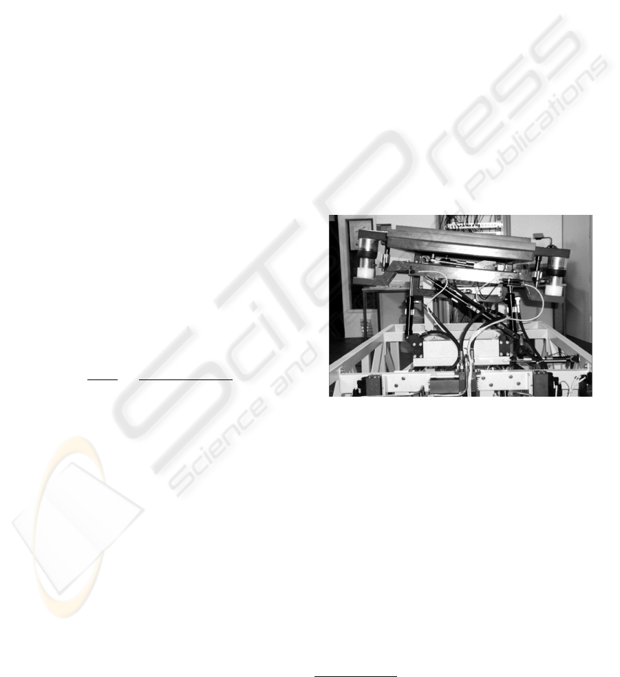
To test the active suspension of the entire vehicle a
testbed was built up in the context of the ”Neue Bah-
ntechnik Paderborn”. This testbed allowed us to de-
sign and test the suspension control (Liu-Henke et al.,
2002). Fig. 5 shows the testbed. Three lower hy-
draulic cylinders serve to simulate track excitations
and are able to impose forces resp. torques in horizon-
tal, vertical, and rotatory directions on the car body.
The upper part represents the suspension/tilt module
as it might be mounted aboard the vehicle. The mass
of the carriage is supported exclusively by airsprings,
as described in section 3.
Figure 5: Suspension-tilt testbed
With the procedure described here a control of the
relative motion between chassis and carriage body is
sufficient. In order to achieve an increase in comfort
one might think of damping the absolute motions of
the carriage body
5
, but this was not included in the
present control because the absolute motions are to
be impacted by the preview algorithm.
Implementation of the Learning Algorithm In or-
der to test the self-optimisation approach presented in
section 4 at the testbed we needed a recurring exci-
tation for a simulation of repeated rides along a fixed
section. For this purpose a track course was defined
that stretched over a 100-m-long track section. For
5
This method known as ”skyhook damping” (Hester-
meyer et al., 2004)
SELF-LEARNING DISTURBANCE COMPENSATION FOR ACTIVE SUSPENSION SYSTEMS
35

determining the objective variables we subdivided the
track section into 100 parts of 1 m each; thus for any
possible moving direction an evaluation vector com-
prising 100 elements was recorded for each crossing.
For an objective we used the maximum of deviations
from the middle position of the car body in the respec-
tive part; it was measured by the existing position-
measuring sensors. One run over the track section in
view takes 10s at an assumed speed v = 10m/s. Af-
ter each crossing the evaluation vectors are transmit-
ted to the learning algorithm which defines the new
trajectories of the disturbance compensation for the
next crossing. These trajectories are parameterised
over 100 supporting points corresponding to the sec-
tions. As shown in fig. 4 the signal f is interpo-
lated between the supporting points. The algorithm
required to determine an optimal disturbance com-
pensation was implemented on a dSPACE real- time
hardware, in addition to the testbed control described.
Here the focus was on testing the learning algorithm.
Difficulties resulting from the necessary communica-
tion between vehicle and processing of information
on the track were ignored here. At the time interval
where the crossing is finished the detected evaluation
variables are transmitted to the optimising procedure
which then computes the new trajectories of the dis-
turbance compensation at exactly the same time in-
terval and makes them available for the next crossing
that begins at the next time interval.
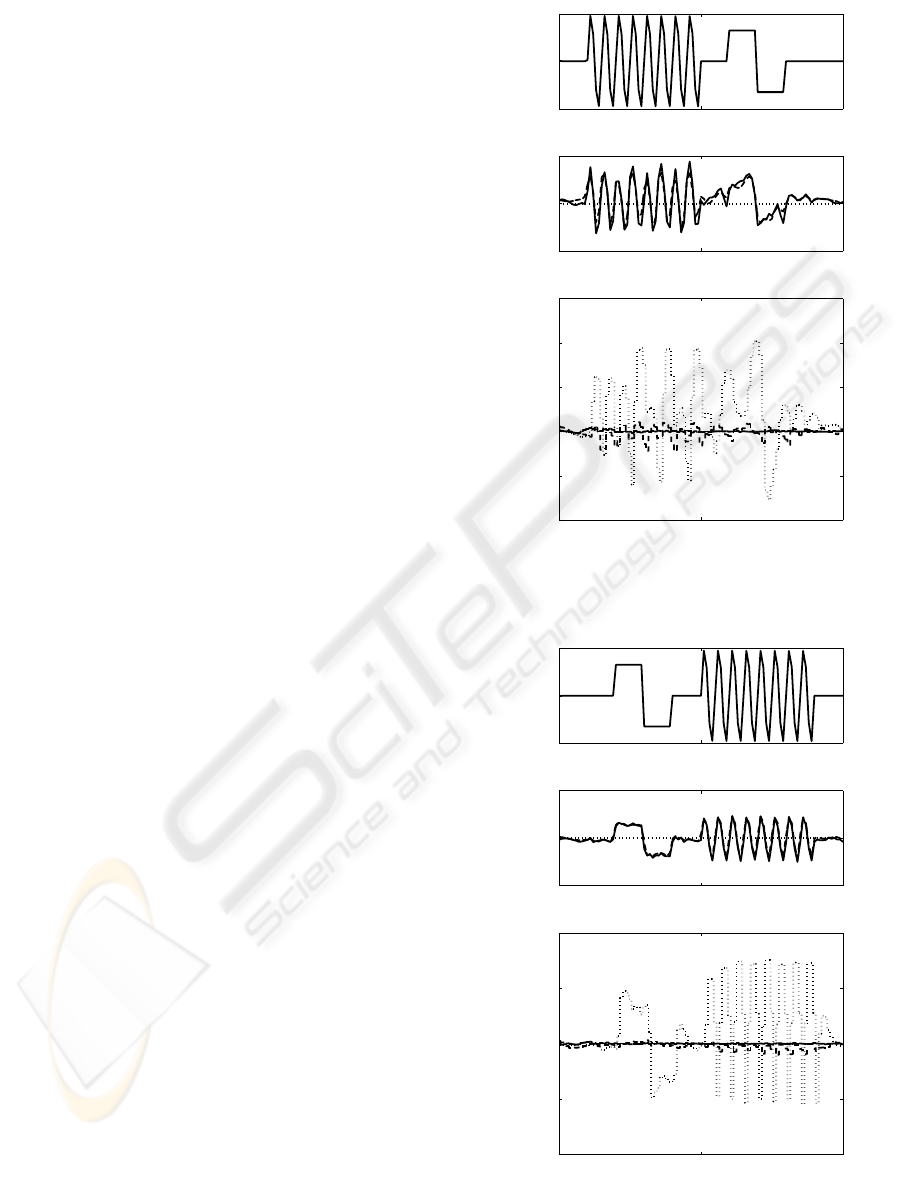
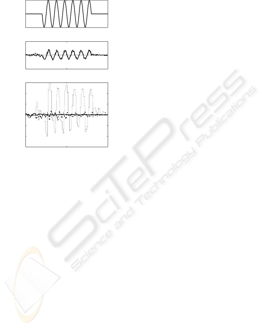
6 RESULTS
This section describes the results of the optimisation
on the basis of measurements at the testbed. The re-
curring excitation over the track section in question is
displayed in Fig. 6 to 8 at the top. In translatory di-
rection the chassis was at first excited by a sinusoidal
signal and subsequently by three steps in lateral direc-
tion resp. inversely in vertical direction. Additionally
a superposed sinusoidal rotation around the longitu-
dinal axis of the chassis took effect. The middle dia-
grams display the disturbance trajectory acquired by
repeated runs in the course of optimisation. The plot
shows the characteristics as follows: at the outset of
the optimisation as a dotted line, after five crossings as
a broken one, and as an unbroken line after 50 cross-
ings. The lower part displays the corresponding plots
of the evaluation functions.
All in all the optimisation method has proved its
ability to compensate the car body movements almost
in full for the periodically recurring excitations. After
only five crossings the amplitudes of the body motion
fell below 10%. After 50 crossings the carriage body
is nearly in a position of rest in spite of the excitation.
Another aspect is made clear in a comparison of
the excitation behaviors and the corresponding dis-
turbance compensation. With a vertical motion these
variables converge while with torsion and lateral mo-
tion there remain significant differences even after 50
repetitions. This is due to the coupling of motions.
A lateral excitation will always bring about a torsion
in the car body; vice versa, a rotation of the chas-
sis around the longitudinal axis will always affect the
lateral motion of the car body. This is why the dis-
turbance compensation has to take into account these
couplings, the result being the behavior shown. On
the other hand, the car body motion in vertical direc-
tion is decoupled from the other degrees of freedom;
thus the disturbance compensation will only have to
deal with the excitation portion in this direction.
7 CONCLUSION
It was shown that using existing data processing in-
frastructure for the exchange of collected data can be
effective for the compensation of recurring stationary
disturbances. The realization at the testbed confirmed
the advantages of this approach. However it may not
be ignored that the trajectories of the compensation
do not represent the disturbances themselves. Rather
they are optimized with respect to the particularly re-
garded vehicle and its velocity. At the testbed this
causes no problem, because the dynamics and the as-
sumed velocity of the testbed does not change during
a test. Of course in reality different vehicles must be
considered. In this case the compensation adapted to
a particular vehicle cannot be used. In order to be able
to use the presented method nevertheless, vehicle and
velocity independent information must be stored. For
this purpose the actual track characteristics are ideal
which can be determined by observation from the re-
spective system response of an individual vehicle. In
this way the approach introduced here can be gener-
alized on different types of vehicles.
Thus the method represents a good way to improve
the dynamic behavior for repetitive motions. It can
also be transferred to other applications, which show
similar characteristics.
To prove the convergence of the learning algorithm
a simplified convergence analysis was performed by
using methods derived from digital control theory.
An enlargement of the convergence model in view of
a concurrent analysis of several supporting points is
possible and will be object of future research.
REFERENCES
Donahue, M. D. (2001). Implementation of an active sus-
pension, preview controller for improved ride com-
ICINCO 2005 - INTELLIGENT CONTROL SYSTEMS AND OPTIMIZATION
36
fort. Master’s thesis, The University at Berkeley.
Hanselmann, H. (1984). Diskretisierung kontinuierlicher
regler. Regelungstechnik, 32(10).
Hestermeyer, T. (2003). railcab - an integrative system
for the 21st century. Urban Tranport International,
(50):24–25.
Hestermeyer, T., Ettingshausen, C., and Schlautmann, P.
(2003). Aktive Federung f
¨
ur Schienenfahrzeuge - Sys-
temaufbau, Regelung und Realisierung. In 5. VDI-
Mechatroniktagung, Fulda, Germany.
Hestermeyer, T., M
¨
unch, E., and Oberschelp, O. (2004).
Sollbahn-Planung f
¨
ur schienengebundene Fahrzeuge.
In Numerical Analysis and Simulation in Vehicle
Engineering, VDI-Berichte 1846, pages 137–158,
W
¨
urzburg.
Ioannou, P. (1998). Evaluation and analysis of automated
highway system concepts and architectures. Cali-
fornia PATH Research Report UCB-ITS-PRR-98-12,
University of Southern California.
J
¨
aker, K.-P. (1990). Entwicklung realisierbarer hi-
erarchischer Kompensatorstrukturen f
¨
ur lineare
Mehrgr
¨
oßensysteme mittels CAD. Number 243 in
VDI-Fortschritt-Berichte, Reihe 8. D
¨
usseldorf.
Liu-Henke, X., L
¨
uckel, J., and J
¨
aker, K.-P. (2002). An ac-
tive suspension/tilt system for a mechatronic railway
carriage. Journal of IFAC, Control Engineering Prac-
tice, (10):991–998.
M
¨
unch, E., Hestermeyer, T., Oberschelp, O., Scheideler,
P., and Schmidt, A. (2004). Distributed optimization
of reference trajectories for active suspension with
multi-agent systems. In European Simulation Mul-
ticonference 2004 - Networked Simulations and Sim-
ulated Networks, pages 343–350, Magdeburg, Ger-
many. SCS.
Rutz, R. (1987). Entwurf eines komplexen
Mehrgr
¨
ossenreglers f
¨
ur die aktive Federung eines
gel
¨
andeg
¨
angigen Nutzfahrzeuges. Master’s thesis,
MLaP, University of Paderborn.
Streiter, R., Boller, M., Riege, B., Schneider, R., and Him-
melstein, G. (2001). Active lateral suspension for high
speed trains - a step towards the mechatronic bogie. In
World Congress on Railway Research, Cologne, Ger-
many.
Zanella, M., Lehmann, T., Hestermeyer, T., and Pot-
tharst, A. (2002). Deterministic and high-performance
communication system for the distributed control of
mechatronic systems using the ieee1394a. In World
Computer Congress, Stream 7, DIPES, Montreal.
0 50 100
−0.01
0
0.01
excit
y
[m]
0 50 100
−0.02
0
0.02
comp
y
[m]
0 50 100
−0.02
−0.01
0
0.01
0.02
0.03
s [m]
obj
y
[m]
Figure 6: Evaluation: lateral
0 50 100
−0.01
0
0.01
excit
z
[m]
0 50 100
−0.02
0
0.02
comp
z
[m]
0 50 100
−0.02
−0.01
0
0.01
0.02
s [m]
obj
z
[m]
Figure 7: Evaluation: vertical
SELF-LEARNING DISTURBANCE COMPENSATION FOR ACTIVE SUSPENSION SYSTEMS
37
0 50 100
−0.02
0
0.02
excit
alpha
[rad]
0 50 100
−0.05
0
0.05
comp
alpha
[rad]
0 50 100
−0.03
−0.02
−0.01
0
0.01
0.02
0.03
s [m]
obj
alpha
[rad]
Figure 8: Evaluation: rotatory
ICINCO 2005 - INTELLIGENT CONTROL SYSTEMS AND OPTIMIZATION
38
