
CONTINUOUS NAVIGATION OF A MOBILE ROBOT WITH AN
APPEARANCE-BASED APPROACH
Luis Payá, M. Asunción Vicente, Laura Navarro, Oscar Reinoso, César Fernández, Arturo Gil
Departamento de Ingeniería de Sistemas Industriales, Miguel Hernández University, Av. de la Universidad s/n,
Ed. Torreblanca, 03202, Elche (Alicante), Spain
Keywords: Automated learning, Continuous navigation, Appearance-based method, View-sequence route-
representation.
Abstract: Appearance-based approaches have become a feasible technique applied to robot navigation. They are based
on the direct comparison of images without any feature extraction. This approach presents several
advantages comparing to model-based methods, such as their application to non-structured environments
and the relative simplicity of the control they offer. This work presents the continuous navigation of a
mobile robot, using an appearance-based method. The objective is the following of pre-recorded routes,
using just visual information acquired with a couple of parallel cameras. In this approach, low-resolution
frontal images along the route to follow are stored. This is done in an automated way, what allows
optimizing the database size. Several control schemas have been tested to improve the accuracy in the
navigation, such as P, PD and PD with variable parameters, whose experimental results are presented.
1 INTRODUCTION
Conventional research on mobile robots has focused
on approaches that use geometric models to
outperform auto-location and navigation (Lebegue,
1993), (Swain 1999). These techniques make use of
landmarks from the scene as references to guide the
robot through the desired route. The recognition of
patterns is achieved comparing features of the input
image with previously stored features. It supposes
high complexity due to the difficulty in features
extraction and comparison of patterns in realistic and
changing environments.
In appearance-based approaches, images are
memorized without any feature extraction, and
recognition is achieved based on the matching of the
images. It is expected to be useful for complicated
scenes in the real world in which appropriate models
for recognition are hard to create. This approach
consists on two phases; in the learning one, the robot
stores general visual information from several points
of view in the environment, and in the autonomous
navigation, a control action is calculated comparing
the current visual information with the stored one.
These techniques require huge amounts of
memory and high computational cost to store the
necessary information of the environment and make
the comparisons, so researchers have proposed
several methods to outperform auto-location and
navigation trying to minimize the database and the
computing time. Matsumoto et al. addressed the
VSRR (View Sequence Route Representation)
method (Matsumoto, 1996), consisting on the direct
comparison of low-resolution images. Jones et al.
proposed a method using a couple of cameras and
odometer information to carry out navigation (Jones,
1997). The computing time can be reduced working
with the colour histogram instead of the entire image
(Zhou, 2003). Also the complexity of the problem
can be reduced working in the PCA subspace
(Maeda, 1997).
The method proposed is based on the VSRR
model with a couple of cameras, in which the size of
the images to store is reduced by taking a low
resolution, and the size of the database is optimized
using an automated learning phase.
2 CONTINUOUS NAVIGATION
USING LOW-RESOLUTION
IMAGES
The application has been tested over the B21r
mobile robot, which has 4-wheel drive with
synchronous drive kinematics. The driving and the
443
Payá L., Asunción Vicente M., Navarro L., Reinoso O., Fernández C. and Gil A. (2005).
CONTINUOUS NAVIGATION OF A MOBILE ROBOT WITH AN APPEARANCE-BASED APPROACH.
In Proceedings of the Second International Conference on Informatics in Control, Automation and Robotics - Robotics and Automation, pages 443-446
DOI: 10.5220/0001184204430446
Copyright
c
SciTePress
steering systems can be controlled independently.
The images are acquired using a couple of Sony
XC999 cameras with their optical axis aligned. The
simultaneous use of two cameras will make our
method more robust.
Previous experiments with 32x32, 64x64 and
128x128 resolutions showed that 32x32 is a good
value due to the low computational cost it supposes,
although it slightly increases the error in the
following (Payá, 2005).
The purpose of the work is to follow pre-
recorded continuous routes. To achieve this, two
phases need to be implemented: a learning stage, in
which some visual information along the route is
stored, and an autonomous navigation phase, in
which the robot estimates its current position and
drives to tend to the learned route.
2.1 Learning phase
In our previous work (Payá, 2005), the route was
decomposed in straight segments before carrying out
the learning phase. Then, the robot was manually
guided through the route to learn, taking images
along the decomposed route in the points the
operator decided. This fact made necessary to store,
apart from the images, the qualitative control action
(left or right) that the robot should execute in the
intersection of two adjacent segments. This way, in
the navigation phase, when the robot arrived to one
of these intersections, it had to stop and begin a pure
turning movement. As well, the separation between
two samples (and so, the size of the database) was
decided by the operator.
The model presented proposes a new learning
method that makes possible continuous navigation,
with no need of storing additional information apart
from the images along the route. Besides, to
optimize the size of the database, the learning phase
has been automated. This means the robot takes
images simultaneously with both cameras at the first
point of the route, and compares continuously the
current views with those previously stored. The
criterion used is the zero-mean cross-correlation.
When the correlation of the current images respect
to the previous stored goes down a threshold, a new
pair of images are acquired and stored in the
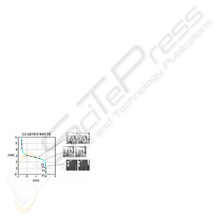
database. Fig. 1 shows a possible route with the
points where images have been taken. In the straight
zones, the views change slowly, so new images are
stored with less frequency. When the robot is
turning, the information changes quicker, so the
images are stored more frequently.
2.2 Autonomous navigation
During the autonomous navigation, the robot is
located in a point near the learned route. Then, it has
to recognize which of the stored positions is the
nearest to the current one and drive to tend to the
route, following it till the end. Two processes that
are executed successively have been implemented:
auto-location and autonomous navigation.
Auto-Location: To carry out auto-location, the
current entire images are compared using the zero-
mean cross-correlation with all those previously
stored in the database (Payá, 2005).
During the navigation, the current image must be
compared only with the previously matched and the
following one, because navigation is continuous.
This implies that, once the robot has started
navigation, the time of processing is independent of
the database size, and so, of the length of the route to
be followed.
Control: The robot steering has to be corrected to
make it tend to the route and follow it to the end. It
is achieved through the tracking of two sub-windows
taken on the matched images over the current
images, as shown on fig. 2. The offsets x
l
and x
r
allow calculating the necessary steering velocity.
The linear velocity will be proportional to the
average correlation, what means that when the robot
is far from the route, the linear velocity is low to
allow correcting the trajectory, but when the route is
being followed quite well, the robot goes quicker.
This equals to a proportional controller (eq. 1).
(1)
Being k
l
, k
r
and k
2
three constants. Taking into
account the results experimentally obtained in our
previous works (Payá, 2005), the given value to the
constants is: k
l
= k
r
= 0.04 and k
2
= 0.6. γ
av
is the
arithmetic average of the correlations of the left and
right images. Fig. 3 shows the typical evolution of
the correlation during autonomous navigation.
.
.
2
i
av
i
i
rr
i
ll
i
kv
xkxk
γ
ω
⋅=
⋅+⋅=
Fi
g
ure 1: Database created durin
g
learnin
g
sta
g
e
ICINCO 2005 - ROBOTICS AND AUTOMATION
444
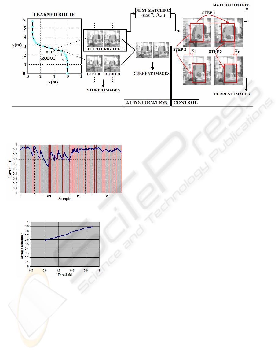
The vertical lines indicate the points where the
matching images change. When this occurs,
correlation begins increasing, reaches a maximum
when he passes through the point where images
were stored and begins decreasing until the next
images are matched. Then, this behaviour is
repeated. The average value of this correlation along
the navigation can be used as a measure of the
accuracy in the route following respect the pre-
recorded one. After several experiments with
different values for the learning threshold, the results
obtained are shown on fig. 4.
To improve the behaviour during navigation,
trying to perform it with a better degree of
correlation, several control schemas have been
tested. The second control schema includes
differential effects in the control of linear and
angular speeds.
(2)
The effect this controller has in the navigation is
a foresight of what is going to happen. In the case of
the linear velocity, when the correlation is
increasing, the robot is approaching to the route
correctly. In this case, the derivative factor is
positive, what means that the robot goes quicker
because it is tending to the route correctly. When
correlation decreases, the derivative factor is
negative, so the robot reduces its velocity because it
is moving away the route. This foresight effect can
be applied to the turning speed too. This means that
the differential effect may improve the overall speed
during the navigation and the overall error in the
following of the learned route. This second effect
can be appreciated on fig. 5.
The last control schema tested is based in the
differential one, but making the parameters variable.
(3)
In this control schema, the effect of the
horizontal offset of the left sub-windows is
[
]
(
)
(
)
[
]
()
.
.
1
22
11
11
−
−−
−⋅+⋅=
−+−⋅++⋅=
i
av
i
avD
i
av
i
i
r
i
r
i
l
i
lD
i
r
i
l
i
kkv
xxxxkxxk
γγγ
ω
Figure 2: Tasks performed during autonomous navigation. First one, the robot makes auto-location, comparing
current images with the previously matched, and the next ones. Once we have a match, we calculate, the linear
and steering speeds based o the global correlation and the horizontal displacement of a template
[
]
()()
[]
()
.
.
1
22
11
1
1
−
−−
−⋅+⋅=
−⋅+−⋅⋅+
+⋅+⋅⋅=
i
av
i
avD
i
av
i
i
r
i
r
i
r
i
l
i
l
i
lD
i
r
i
r
i
l
i
l
i
kkv
xxxxk
xxk
γγγ
γγ
γγω
Figure 4: Average correlation during navigation for
different learning thresholds
Figure 3: Evolution of correlation during navigation
CONTINUOUS NAVIGATION OF A MOBILE ROBOT WITH AN APPEARANCE-BASED APPROACH
445
multiplied by the correlation of the current left
image with the matched left one, and the same with
the right offset. This schema can be useful when the
images of each camera are quite different or when
there is an obstacle or occlusion that affects just to
one of the cameras. In these cases, the control action
of the camera that has the problem will be multiplied
by a very low quantity, so it will have a poor effect
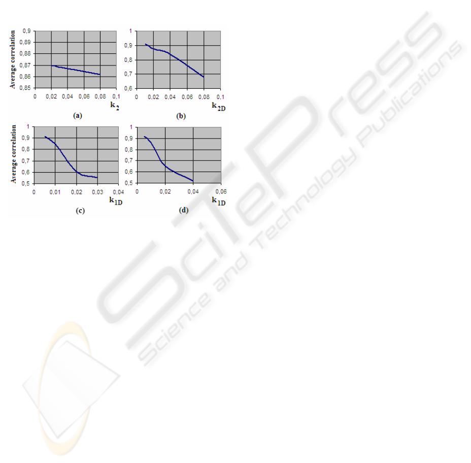
on the robot navigation. As well, the experiments
that have been carried out show how this control
schema improves slightly the results that offers the
differential one. These results are shown in fig. 5.
3 CONCLUSIONS AND FUTURE
WORK
A solution to the problem of the continuous
navigation using an appearance-based approach has
been proposed. Several control schemas have been
tested, including P, PD and PD with variable
parameters controllers. With these laws, the robot is
able to find itself and follow the route in a band of
about two meters around the pre-recorded route. It
can be done although the scene suffers small
changes (illumination, position of some objects,
partial occlusions in one of the cameras). We are
now working in other control methods, such fuzzy
logic.
The main drawback of this navigation method
arises when the scenes are highly unstructured and
varying. In this case, it is necessary to increase
resolution to get an acceptable accuracy in
navigation. The solution proposed is based in the
reduction of the information to store using PCA
subspaces. This method shows two big advantages:
the size of the vectors to compare is much smaller
and we can calculate the majority of the information
off-line so we have it available during navigation.
Besides, the size of the vectors is independent of the
resolution of the images so, it is expected to work
well in very unstructured environments.
ACKNOWLEDGEMENTS
This work has been supported by Ministerio de
Educación y Ciencia through project DPI2004-
07433-C02-01. ‘Herramientas de teleoperación
Colaborativa. Aplicación al Control cooperativo de
Robots’.
REFERENCES
Jones, S.D., Andersen, C., Crowley, J.L., 1997.
Appearance based processes for visual navigation. In
Proceedings of the IEEE International Conference on
Intelligent Robots and Systems. 551-557.
Lebegue, X., Aggarwal, J.K., 1993. Significant line
segments for an indoor mobile robot. In IEEE
Transactions on Robotics and Automation. Vol. 9, nº 6,
801-815.
Maeda, S., Kuno, Y., Shirai, Y., 1997. Active navigation
vision based on eigenspace analysis. In Proceedings
IEEE International Conference on Intelligent Robots
and Systems. Vol 2, 1018-1023.
Matsumoto, Y., Inaba, M., Inoue, H., 1996. Visual
navigation using view-sequenced route representation.
In Proceedings of IEEE International conference on
Robotics and Automation. Vol 1, 83-88.
Ohno, T., Ohya, A., Yuta, S., 1996. Autonomous
navigation for mobile robots referring pre-recorded
image sequence. In Proceedings IEEE International.
Conference on Intelligent Robots and Systems. Vol 2,
672-679.
Paya, L., Reinoso, O., Gil, A., Garcia, N., Vicente, M.A.,
2005. Accepted for 13
th
International Conference on
Image Analysis and Processing.
Swain-Oropeza, R., Devy, M., Cadenat, V., 1999.
Controlling the execution of a visual servoing task. In
Journal of Intelligent and Robotic Systems. Vol 25, No
4, 357-369.
Zhou, C., Wei, T., Tan, T., 2003. Mobile robot self-
localization based on global visual appearance features.
In Proceedings of the 2003 IEEE International
Conference on Robotics & Automation. 1271-1276.
Figure 5: Average correlation during navigation for
different control schemes. (a) P controller with K
l
= K
r
=
0.04. (b) P controller with derivative effect in advance
speed. K
2
= 0.04. (c) PD controller with K
2
= 0.04 and
K
2D
= 0.04. (d) PD controller with variable parameters, K
2
= 0.04 and K
2D
= 0.04
ICINCO 2005 - ROBOTICS AND AUTOMATION
446
