
TOPOLOGICALLY ROBUST RECONSTRUCTION OF A 3D
OBJECT WITH ORGANIZED MESHING
Junta Doi, Wataru Sato
Department of Computer Science, Chiba Institute of Technology, Narashino, Japan
Keywords: 3D reconstruction, Polygonal scanning, Organized meshing, Quadrilateral mesh, Hexagonal mesh, Matrix
format data structure, 3D shape modification, Topology conserved reconstruction.
Abstract: This paper proposes a practical, topologically robust and ranging error resistive shape modeling procedure
that approximates a real 3D object with the matrix-formatted organized meshing for the 3D shape processing.
A geometric model with desired meshing, not limited to triangular one, but also quadrilateral, hexagonal or
n-gonal mesh, is directly reconstructed based on a solid modeling approach. The radial distance of each scanning
point from the axis of the cylindrical coordinates is measured by laser triangulation. The angular and vertical
positions of the laser beam are two other coordinate values of the scanning. A face array listing (topology),
which defines the vertex (sampling point) connectivity and the shape of the mesh, is assigned to meet the
desired meshing. Stable meshing, and hence, an accurate approximation, free from the shape ambiguity
unavoidable in the widely used ICP (Iterative Closest Point) modeling, is then accomplished. This proposal
allows a practical and versatile reconstruction and the successive 3D shape modification.
1 INTRODUCTION
The problem of shape reconstruction has been the
focus of research across many fields because of its
wide applications. Attempts to measure the shape of
objects and to construct geometric models have a
long history. There are a great number of books
(Mantyla, 1988, Hartley et al., 2000, and Forsyth et
al., 2003), review articles (Chen et al., 2000, Scott et
al., 2003, and Blais, 2004), papers (Besel, 1992, Turk
et al., 1994, Levoy et al., 2000, Rusinkiewicz et al.,
2001, Godin et al., 2002, Pauly et al., 2003, and Dey
et al., 2004), and products (Simple3D, 2005) dealing
with the problems.
This study is to provide technology that would
reconstruct the objects, such as, cultural heritage
artifacts and reliefs, accurately and precisely as they
are in a usually noisy environment. A 3D shape
processing for reuse of the geometric models is our
purpose of the proposal.
Surface models with unorganized triangular
meshes have been built based on the ICP algorithm
from the scanned cloud points obtained by, for
instance, triangulation scanners so far. A great deal of
research efforts has been made on the problem. The
ICP algorithm is widely used and well proven in
some applications; however, it is ranging-noise
sensitive and hence shape-ambiguous, and compli-
cated for constructing a fully automated system.
In general, the presence of noise (the ranging
noise or triangulation error) is typical for the
scanning process. Retrieving surface topology from
surface geometry as the algorithm is not easy, when
the ranging noise is unavoidable. Many attempts have
been made to overcome the problem; however, there
is no known algorithm that has theoretical guarantees,
without assumptions, for surface reconstruction in the
presence of noise (Dey et al., 2004).
The triangulation error arises mostly from the
oblique reflection of the incident laser beam on the
local surface. To reduce the error, a large object
model with rather flat surfaces is to be employed. The
surface polishing is most effective for an error-free
and reliable triangulation. These measures are,
however, not applicable to most of the objects that
should be treated as they are.
Contrary to the widely used procedures, this
paper proposes an approach such that the surface
topology is first assigned and a geometric model with
a solid model format with the desired meshing is
directly generated.
In other words, the method involves a proto-
typical model (e.g., the unit cylinder in Fig. 1) being
first prepared by considering the shape of the object
154
Doi J. and Sato W. (2005).
TOPOLOGICALLY ROBUST RECONSTRUCTION OF A 3D OBJECT WITH ORGANIZED MESHING.
In Proceedings of the Second International Conference on Informatics in Control, Automation and Robotics - Robotics and Automation, pages 154-159
DOI: 10.5220/0001179001540159
Copyright
c
SciTePress
and then modifying every mesh point to reflect the
geometric shape of the object. This is “topology is
first and then geometry” not that “geometry first and
then topology” as the IPC modeling.
This model is called “B-reps (Boundary repre-
sentations)” which describes a 3D object as a set of
surfaces that separate the object interior from the
environment and is a polygon mesh approximation of
a curved object surface.
Usually, irregular triangular meshes, generated,
for instance, by the algorithm, are re-sampled into
regular meshes when required. However, point-
locatable nature and accuracy are lost in the
re-meshing process. Very many scientific efforts are
focused on the unorganized meshing, however, to our
knowledge; few published works that can be related
to this proposal of organized meshing have been
presented.
During morphing or warping, which is a funda-
mental operation in computer graphics, the initially
constructed model is deformed into another model.
Usually it is computer-graphics-based and operation
is applied to unorganized triangular meshes, which
are not surface-point-position- locatable.
O
O
u
u
r
r
s
s
h
h
a
a
p
p
e
e
d
d
e
e
f
f
o
o
r
r
m
m
a
a
t
t
i
i
o
o
n
n
i
i
s
s
a
a
p
p
p
p
l
l
i
i
e
e
d
d
t
t
o
o
t
t
h
h
e
e
o
o
r
r
g
g
a
a
n
n
i
i
z
z
e
e
d
d
a
a
n
n
d
d
p
p
o
o
i
i
n
n
t
t
-
-
l
l
o
o
c
c
a
a
t
t
a
a
b
b
l
l
e
e
m
m
o
o
d
d
e
e
l
l
,
,
o
o
r
r
i
i
g
g
i
i
n
n
a
a
t
t
e
e
d
d
f
f
r
r
o
o
m
m
t
t
h
h
e
e
m
m
o
o
d
d
e
e
l
l
i
i
n
n
g
g
p
p
r
r
o
o
c
c
e
e
d
d
u
u
r
r
e
e
,
,
u
u
s
s
i
i
n
n
g
g
i
i
n
n
t
t
u
u
i
i
t
t
i
i
v
v
e
e
m
m
a
a
t
t
r
r
i
i
x
x
-
-
t
t
y
y
p
p
e
e
o
o
p
p
e
e
r
r
a
a
t
t
o
o
r
r
s
s
e
e
n
n
a
a
b
b
l
l
i
i
n
n
g
g
t
t
h
h
e
e
q
q
u
u
a
a
n
n
t
t
i
i
t
t
a
a
t
t
i
i
v
v
e
e
s
s
h
h
a
a
p
p
e
e
m
m
o
o
d
d
i
i
f
f
i
i
c
c
a
a
t
t
i
i
o
o
n
n
,
,
e
e
v
v
a
a
l
l
u
u
a
a
t
t
i
i
o
o
n
n
a
a
n
n
d
d
C
C
A
A
D
D
c
c
o
o
m
m
p
p
a
a
t
t
i
i
b
b
i
i
l
l
i
i
t
t
i
i
e
e
s
s
.
.
Laser triangulation sensors using the spot and
stripe projections are used for the examples in this
paper, but the measurement procedure is general and
not limited to these. As a modeling/rendering system,
we prepared some solid model interfaces for popular
computer graphics or computer-aided design
systems.
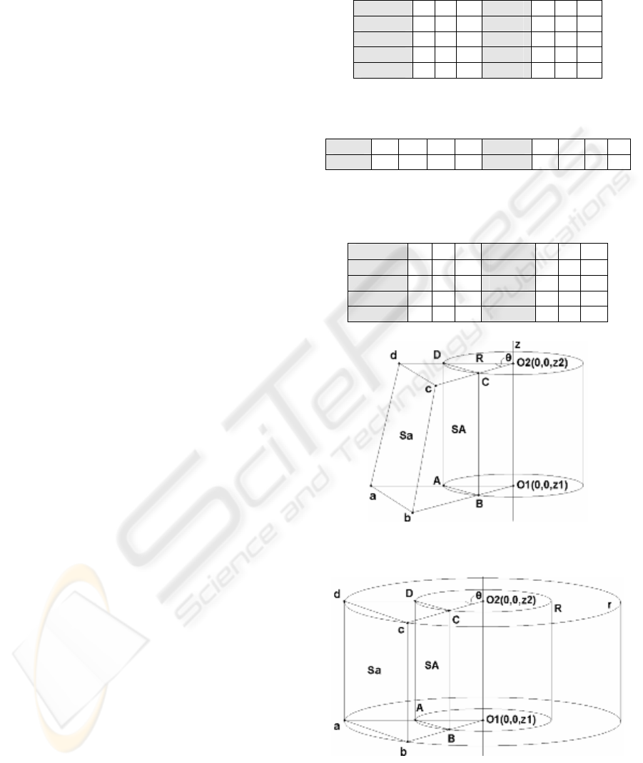
2 SOLID MODELING
In the illustration of a solid model data structure in
Fig. 1, a pentahedral volume element, in which the
peripheral surface is covered with a rectangular mesh,
small enough to approximate the curved object
surface, is to be measured to approximate the object
shape. A quadrilateral mesh Sa, consisting of four
surface points, a, b, c and d, is one of the sampling
points on the object surface. Points A, B, C and D are
mesh points consisting of a rectangular mesh SA on
the unit cylinder surface. The rectangu- lar mesh SA
is a perspective projection of the quadrilateral mesh Sa
to the unit cylinder surface, and vice versa. Each radial
distance of the object surface point from the axis of
rotation (z-axis), for instance, “r
a
, r
b
, ···” is
sequentially measured. We call this type
Table 1: Vertex array listings (geometry) for the rectan-
gular surface mesh SA (left, on the unit cylinder surface)
and the quadrilateral Sa (right, on the object surface) in Fig. 1.
Vertex r θ z Vertex r θ z
SA: A
1 0 z
1
Sa: a
r
a
0 z
1
B
1 θ z
1
b
r
b
θ z
1
C
1 θ z
2
c
r
c
θ z
2
D
1 0 z
2
d r
d
0 z
2
Table 2: Face array listings (topology) for the mesh SA (on
the unit cylinder) and Sa (on the object surface) in Fig.1.
Table 3: Vertex array listings (geometry) for the quadri-
lateral mesh SA (left, on the object surface) and the rectan-
gular mesh Sa (right, on the unit cylinder surface) in Fig. 2.
Vertex
r θ z
Vertex
r θ z
SA: A r
a
0 z
1
Sa: a 1 0 z
1
B r
b
θ z
1
b 1 θ z
1
C r
c
θ z
2
c 1 θ z
2
D r
d
0 z
2
d 1 0 z
2
Figure 1: The mesh structure of a solid model cylinder for
scanning of an object on the axis (object-modeling mode).
Figure 2: The mesh structure of a solid model concentric
cylinder for the outer scene scanning (scene-modeling mode).
The outer cylinder with a radius “r” is a cut-off limit of the
ranging sensor. A quadrilateral mesh “SA” is on the object
surface. “Sa” is a rectangular mesh on the cut-off cylinder.
Face 1 2 3 4 Face 1 2 3 4
SA(u) B C D A Sa(o) b c d a
TOPOLOGICALLY ROBUST RECONSTRUCTION OF A 3D OBJECT WITH ORGANIZED MESHING
155
of modeling the “object-modeling mode.”
A vertex array listing, which is called “geometry”
and represents the geometric coordinate values in 3D
space is shown in Table 1. The face (mesh) array
listings for the Sa and SA are shown in Table 2.
Other four comprising surfaces of the wedge shaped
pentahedral volume element are similarly defined
(Tables not shown). The listing is called “topology”
and defines the shape of the face (number of vertices
or edges) and also defines the listing sequence of the
vertices or connectivity. The listing sequence of the
vertices in the face list defines the normal vector
direction of the face and determines on which side of
the face the solid part of the object exists. This mesh
is directly compatible with that used in the BEM
(Boundary Element Method).
As shown in Fig. 1 and Table 2, the variation in
the radial distance (depth) of a, in principle, has no
effect on the connectivity array of the face, if point a
locates along the radial line segment O1-a or O1-A.
This relation is also valid for the other points b, c,
and d as well. Therefore, the connectivity array of the
mesh is conserved if the four points similarly locate
along each radial line. The vertex connectivity of Sa
is the same as that on the unit cylinder, SA as shown
in Fig. 1 and Table 2. This means that the face array
listing assigned for the unit surface SA is valid for the
object surface Sa. N-gonal meshes are similarly
constructed (Doi et al., 2004).
When the triangulation sensor is set at the axis of
the coordinate and rotates to measure the distance to
the outside scene, the solid modeling is as shown in
Table 3 and Fig. 2, where the object surface is SA and
the mesh is defined on a cut-off circle or a unit circle.
A Boolean subtraction of a pentahedron including SA
from that including Sa results in a hexahedral
element in a solid model of the scene. We call this the
“scene-modeling mode.” The modeling procedure is
similar to the “object- modeling mode.”
Our mesh shape is arbitrary. In this procedure, it
is triangular, quadrilateral, hexagonal or even n-gonal,
if required for a more reduced number of meshes.
Figure 3 shows a hexagonal mesh. Our hexagonal
meshing is based on a 1/2 interlacing scan as shown
in the figure, similar to that of the NTSC video format.
A hexagon can be broken down into six small
triangular meshes, one is, for instance ABG, or two
trapezoids, for instance, ABCF, or three rhomboidal
meshes, for instance, GDEF. The combination of
hexagonal, rhomboidal and triangular meshes is
useful to efficiently cover the variously curved object
surfaces with a reduced number of meshes.
Our data format is a raster scan type or a matrix
format according to the above procedure as described
Figure 3: An example of a hexagonal mesh ABCDEF, which
is consisted of two trapezoidal ABCF and DEFC, three rhom-
boids, such as, BCDG, and six triangles, such as, ABG.
Three horizontal scan lines, (L-1), (L) and (L+1) make a
hexagonal mesh. A sequential scan makes a rectangular mesh.
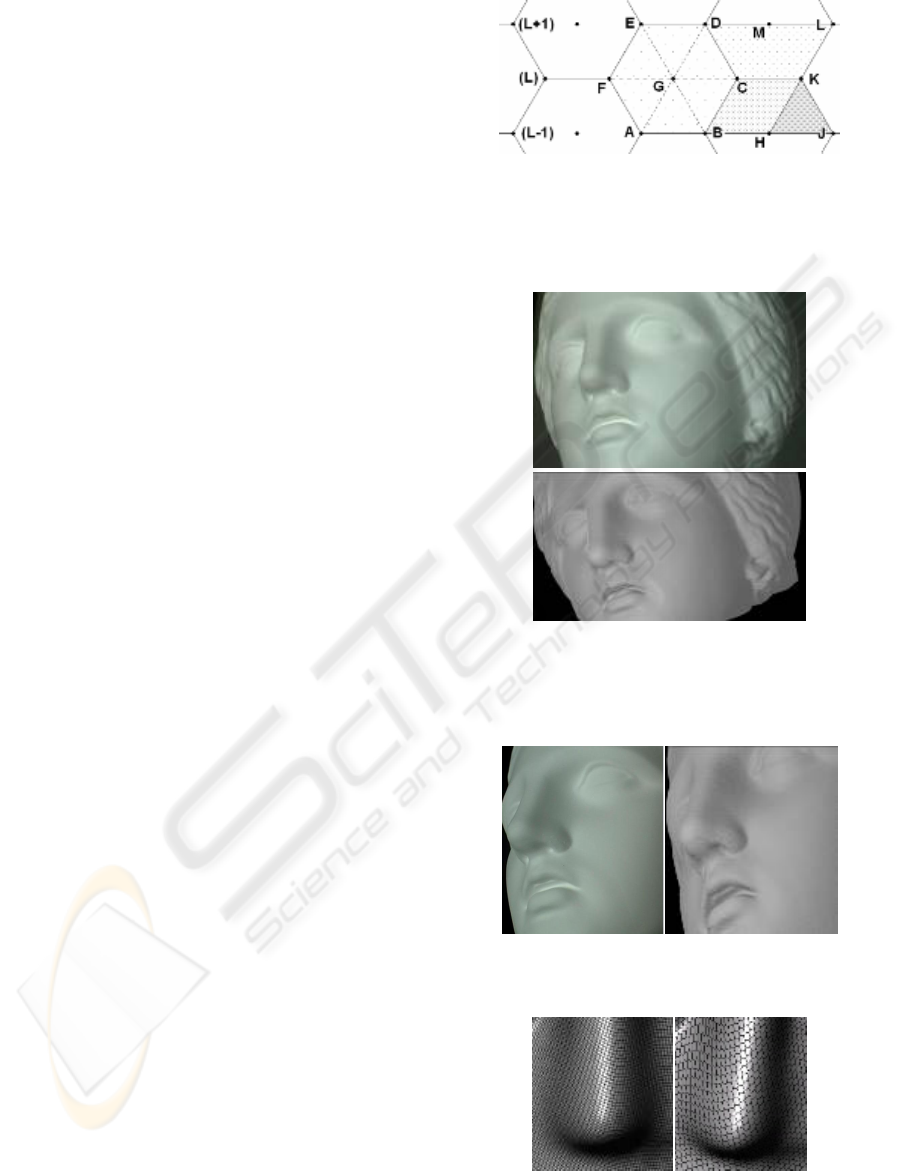
Figure 4: Photograph of the object sculpture head (Niobe)
(top) and the shaded image of the object-modeled result
(bottom). Angular scanning step is 0.4 degrees in the frontal
region (rear; 0.8 degrees)and vertical step is 0.45 mm
Figure 5: Photograph of the object sculpture shown above
(left) and the shaded image of the modeled result (right).
Figure 6: Shaded images of the modeled nose part of the
sculpture (Niobe). Modeled result with overlaid
quadrilateral meshes (left) and hexagonal meshes (right).
ICINCO 2005 - ROBOTICS AND AUTOMATION
156
above and it is as follows.
r = [r
ij
] =
⎥
⎥
⎥
⎦
⎤
⎢
⎢
⎢
⎣
⎡
nmn2n1
2m2221
1m1211
rrr
rrr
rrr
"
#%##
"
"
(1)
An element r
ij
represents the radial distance of a
sampled surface point at the angular position “j” and
at the vertical position “i” in the scanning This matrix
can easily locate an arbitrary point on the object only
by specifying “i” and “j.”
An object such as a sculpture is placed on a turn-
table which is driven by a geared pulse motor with
angular resolution of 0.02 degrees. This means that
the horizontal resolution is 0.015 mm at the radius of
43 mm and there are a maximum of 18,000 horizontal
meshes in one 360 degree turn. The translational
resolution of the vertical slider, which is also driven
by a geared pulse motor, is 0.015 mm with a
maximum stroke of 500 mm. There are 33,333
vertical meshes at maximum in the full stroke.
Therefore, the maximum number of the quadrilateral
meshes is 600 million. In our 600 mega-cloud-points,
each mesh contains additional RGB color
information.
In the demonstrations hereafter, however,
rendering points are reduced to 1/10 in horizontal,
1/10 in vertical and 1/100 of the scanned points in
total, which is about 6 mega-points, for a file size
reduction and quick rendering.
A triangulation sensor with a 690-nm diode laser
was installed on the vertical slider. The laser power is
15 mW and the spot size on the object surface is about
0.3 mm in diameter. A sensing range from 250 mm to
750 mm is produced here with a resolution of 0.01
mm at best. A laser stripe projector with a line width
of 1 mm was also used. In the proposal, the
measurement procedure is general and not limited to
this type of sensing. As a modeling/rendering system,
we prepared solid model interfaces for the popular
3D computer graphics and computer-aided design
systems.
3 RESULTS AND DISCUSSION
The desired meshing, for instance, the rectangular
mesh SA is first assigned for the sampling point
connection and then the vertex array listing is
continuously updated. Our procedure results in the
“B-reps” model, which describes a 3D object as a set
of the organized meshes.
Photographs of a plaster sculpture (Niobe) are in
Figs. 4 (top) and 5 (left). The object-modeled result is
shown in Figs. 4 (bottom) and 5 (right). The result is
estimated to be accurate in an extent of the resolution
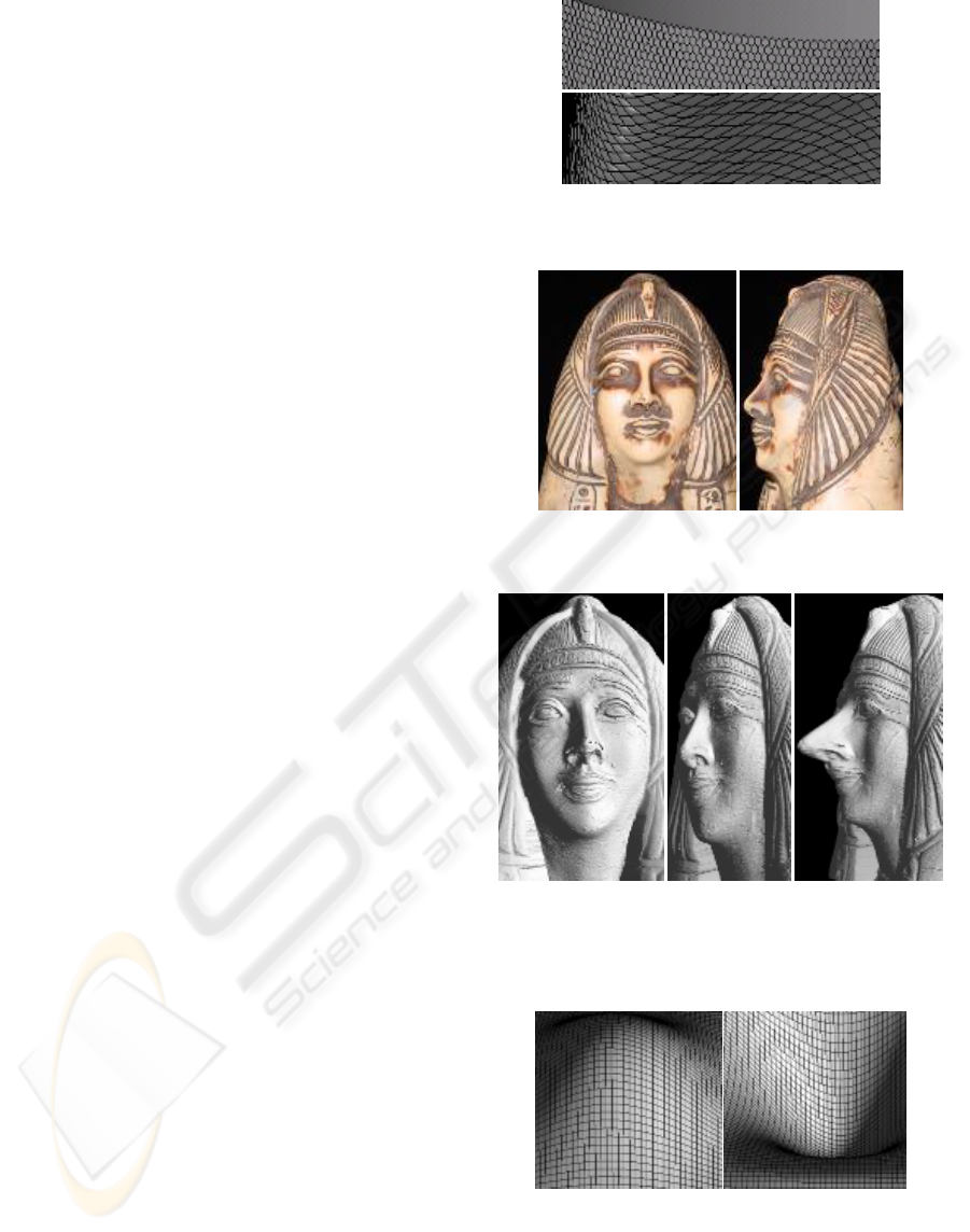
Figure 7: Hexagonal meshes on the unit cylinder in Fig. 2
(top) and rhomboidal meshes made from the hexagons.
Figure 8: Photographs of an object stone sculpture (Cleopatra).
The face is 60 mm high and partly black painted.
Figure 9. Shaded images of the modeled results. A frontal
image (left) and a side image (center), a side image of the
shape modified long nose (right). A 20% of the radial
distance from the axis around the top of the nose is expanded.
Figure 10: Two examples of 128x128 (overlaid wire-frame
representation in 64x64) shape-to-shape (depth-to-depth)
transformation operators. The left figure is positive and the
right negative. The parameter distribution is sinusoidal in
horizontal (peripheral) and vertical directions. They are
configured similarly to the 2D image processing operators.
TOPOLOGICALLY ROBUST RECONSTRUCTION OF A 3D OBJECT WITH ORGANIZED MESHING
157
of 0.015 mm. in all three directions.
Figure 6 (left) is an example of the modeled result
with quadrilateral mesh. Here, triangulation is based
on the laser light stripe projection. It is not as accurate
as the laser spot triangulation. An example of the
modeled result with hexagonal meshes is shown in
Fig 6 (right). An example of the hexagonal meshes on
the unit cylinder is illustrated in Fig. 7 (top) and an
example of the rhomboidal meshes from the
hexagonal meshes is in Fig. 7 (bottom).
Photographs of a stone sculpture (Cleopatra) are
shown in Fig. 8. Some ranging noises are observed in
the modeled result (Data not shown). In spite of the
noises, the surrounding mesh points are observed as
unaffected, showing that each noise is standing alone
and isolated, and the topology is robust and
unchanged as expected from the modeling procedure
explained previously. The smoothed model is shown
in Figs. 9 (left) and 9 (center).
A 3x3 or 5x5 depth-to-depth transformation
operator, which is similar to a two-dimensional
smoothing operator, is sequentially applied to the
matrix-type output data. If the noise is detected, the
point is replaced with the surrounding data.
The matrix type data is convenient and essential
for modifying a local shape when locating the target
position. In Fig. 8 (right), the nose of the statue is
modified in shape and size. Referring to the initial
model in Fig. 8 (center), the modifications are
three-dimensionally applied and evaluated. This is
supposing the restoration of a broken artifact, for
instance, the addition of a lost nose, or for virtual
training of, for instance, cosmetic surgery. In the
figure, a 128x128 depth-to-depth transformation
operator, shown in Fig. 10 (left), similar to the image
intensifying operator, is applied.
The modeled result may be used again as an
operator. Two examples are shown in Fig. 11. One is a
rectangular matrix in the cylindrical surface and the
other is a recursive operator generated by this
modeling procedure for use in convolution or 3D
shape fusion. This is not the so called morphing
operation but the quantitative 3D shape operation
with CAD compatibility.
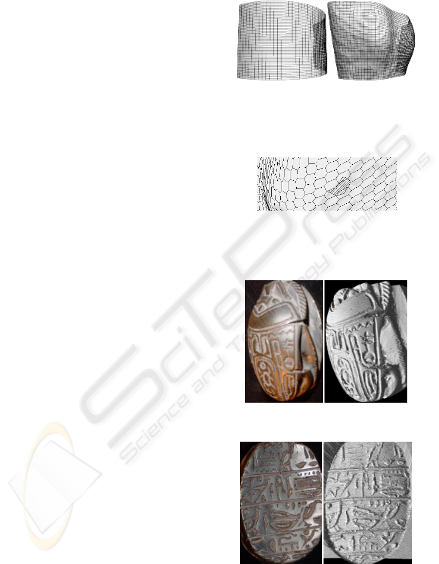
A combination of variously shaped polygons is
used for efficient meshing and watermarking as
shown in Fig. 12. Figure 13 (left) is a photograph of
the backside of a scarab beetle stone and the modeled
result (right). It is about 100 mm long and 70 mm
wide. An underside image of the stone engraved with
hieroglyphs is shown in Fig. 14 (left) and the shaded
image of the modeled result is in Fig 14 (right). It is
an example of the scene-modeling mode. The
modeling is similar to a reconstruction of a relief. In
the comparison, a pictorial image is not the same as
the modeled depth image. It may be concluded that
the depth image is well reproduced in an extent of
Figure 11: A bread arc-board instead of a planar board, such
as Eq. (1) (left), and a customized 3D depth-to-depth
transformation operator, which may be a thus reconstructed
model of a real object based on triangulation. This 3D
shape replaces a part of the initial shape. Convolution of the
reconstructed model operator fuses two shapes together.
Figure 12: An example of polygonal surface comprising of
hexagonal, trapezoidal, rhomboidal and triangular meshes.
A combination of the variously shaped polygons serves the
efficient surface approximation with a reduced number of
meshes and also embedded watermarking.
Figure 13: Backside photograph of the object stone sculpture
(top) and the shaded image of the modeled result (bottom)
Figure 14: Underside photograph of the scarab beetle stone
engraved with hieroglyphs (left) and the shaded image of
the scene-modeled result. The pictorial image is similar but
not the same as the modeled depth image.
ICINCO 2005 - ROBOTICS AND AUTOMATION
158

the 0.015mm resolution.
The modeling accuracy depends on the rotational
and translational positioning, and distance-sensing.
The mal-aligned positioning results in a shape
distortion, but still generates topologically stable
models.
4 CONCLUDING REMARKS
A simple, automatic, geometrically accurate,
topologically stable, robust and noise-resistive object
modeling, with matrix format meshes, to be followed
by quantitative 3D shape processing, is proposed.
Most of the reconstruction procedures from the
unorganized set of points are based on the principle:
“retrieving surface topology from surface geometry.”
In general, “retrieving topology from geometry,”
where appropriate distance-based criteria are used for
the modeling, is not easy especially in the presence of
noise even in the dense data-sets. Our topology, on
the contrary, is not dependent on geometry. In our
procedure, “topology is first assigned in the scanning
stage and geometry follows.” The noise problem is
inherent in the triangulation scanning, which is fatal
in the ICP algorithm due to point-connection
(topology) ambiguities caused by the problem, is
solved using the matrix format smoothing operators
for practical usage in the exchange for some spatial
resolution reduction.
The matrix format of the modeled data is intuitive
and easy to apply to the quantitative shape
modification using the various matrix type 3D shape
modification operators, which recursively include
thus modeled results with the same matrix format.
The 3D shape models are fused together by
convolution. The data format is compatible with that
of the BEM/FEM. The desired meshing, not limited
to triangular, but quadrilateral, hexagonal, and even
n-gonal meshes, is possible in the same way.
A Boolean operation with multi-directional
modeling is currently underway. We expect
considerable utility in the practical approximate
modeling and 3D shape processing.
REFERENCES
Blais, F., 2004, Review of 20 Years of Range Sensor
Development, Journal of Electronic Imaging, 13 (1),
231-240.
Boissonnat, J., 1984, Geometric Structures for Three-
Dimensional Shape Representation, ACM Transactions
on Graphics, 3 (4), 266-286.
Chen, F., Brown, G., Song, M., 2000, Overview of
Three-Dimensional Shape Measurement Using Optical
Methods, Optical Engineering, 39 (1), 10-22.
Dey, T., Goswami, S., 2004, Provable Surface Re-
construction from Noisy Samples, Annual Symposium
on Computational Geometry, In Proceedings of 20th
Annual Symposium on Computational Geometry,
330-339.
Doi, J., Sato, W., Miyamoto, Y., Ando, S., Yamanaka, M.,
2004, Reuse of a Geometric Model for Shape
Approximation, In Proceedings of 2004 IEEE
International Conference on Information Reuse and
Integration (IRI 2004), 174- 179.
Forsyth, D., Ponce, J., 2003, Computer Vision - A modern
Approach, Prentice Hall, New Jersey.
Godin, G., Beraldin, J., Taylor, J., Cournoyer, L.,
El-Hakim, S., Baribeau, R., Blais, F., Boulanger, P.,
Domey, J., Picard, M., Active Optical 3D Imaging for
Heritage Applications IEEE Computer Graphics and
Applications, 22, 24-36, 2002.
Hartley, H.,. Zisserman, A., 2000, Multiple View Geometry
in Computer Vision, Cambridge Univ. Press,
Cambridge, UK..
Levoy,
M., Pulli, K., Curless, B., Rusinkiewicz, S., Koller,
D., Pereira, L., Ginzton, M., Anderson, S., Davis, J.,
Ginsberg, J., Shade, J., Fulk, D., The Digital
Michelangelo Project; 3D Scanning of Large Statues,
In Proceedings of Siggraph 2000, 131-144, 2000.
Mantyla, M., 1988, An Introduction to Solid Modeling,
Computer Science Press, Rockville, Maryland.
Paul J., Besl, P., McKay, D., 1992, A Method for
Registration of 3-D Shapes, IEEE Transactions on
Pattern Analysis and Machine Intelligence, 14 (2),
239-256.
Pauly, M., Keiser, R., Kobbelt, L., Gross, M., 2003, Shape
Modeling with Point-Sampled Geometry, ACM
Transactions on Graphics (TOG), 22 (3), Special issue:
Proceedings of ACM SIGGRAPH, 641-650.
Rusinkiewicz, S.,. Levoy, M., 2001, Efficient Variants of
the ICP Algorithm, In Proceedings of the 3rd
International Conference on 3-D Digital Imaging and
Modeling (3DIM ’01), 145-152.
Scott, W., Roth, G., Rivest, J., 2003, View Planning for
Automated Three-Dimensional Object Reconstruction
and Inspection, ACM Computing Surveys, 35(1),
64-96.
Simple3D, 2005, 3D Scanners, Digitizers, and Software
for Making 3D Models and 3D Measurements,
http://www. simple3d.com/
Turk, G., Levoy, M., 1994, Zippered Polygon Meshes from
Range Images, In Proceedings of SIGGRAPH 1994,
311- 318.
TOPOLOGICALLY ROBUST RECONSTRUCTION OF A 3D OBJECT WITH ORGANIZED MESHING
159
