
TESTBED EVALUATION OF NETWORKED CONTROL
SYSTEMS
George Hassapis, Spyridon Geronatsios and John Grigoriadis
Department of Electrical and Computer Engineering, Aristotle University, 54124 Thessaloniki, Greece
Keywords: Networked Control, Hardware in
the loop simulation, Profibus.
Abstract:
This work addresses the issue of performance evaluation of advanced control algorithms which
are going to be implemented on scalable industrial computer networks. The basic characteristic
of these implementations is that information concerning measurements from sensors, commands
to actuators and reference inputs is exchanged between the plant and the control system over a
real-time communication network. The need to evaluate the performance of such algorithm
implementations before commissioning them derives from the fact that the network-induced
delay during the exchange of the sensor-to-controller and controller-to-actuator data and the
possibility of loss of a data package during transmission may affect the algorithm performance.
One way of assessing this performance is by emulating the operation of the algorithm on a test-
bed. As test-bed is defined the facility that consists of a computer-based simulation of the plant
which is linked to the real communication network and actual control devices on which the
algorithm will be implemented. As there are many proprietary and open communication network
protocols and standards, unavoidably the test-bed has to be constructed for a specific protocol
and standard. In this work a test-bed based on the Profibus standard and its FMS protocol has
been realized. The purpose is the evaluation of a control algorithm which will run on one or
more controllers that will be inserted in an already operating networked control system. In order
to demonstrate the way of using a test-bed for evaluating the performance of a control algorithm
the study of the LQC control of a cement milling circuit is presented.
1 INTRODUCTION
The control systems that have their control loops
closed via a serial and common communication
channel are usually called Networked Control
Systems. They present certain advantages over the
traditional point-to-point architectures, such as
small volume of wiring, distribution of the
processing functions to many units, modularity, low
cost and quick and easy maintenance. However,
they introduce and some new problems arising from
the time varying delay that might appear during the
transmission of sensor and actuator related
measurement data and the possibility of loosing data
during one or more sampling periods. The control
algorithms are usually designed with the assumption
that measurements of the controlled variables can be
taken at sampling rates that are either steady or
varying within certain limits. Because of the
network-induced delays these limits might not be
always secured, something that may influence the
performance of the control algorithm. The same
problem of system stabilization may appear because
some packets of measured or command data not
only suffer transmission delay but even worse, they
can be lost during transmission and they will not
arrive by the time of control calculation.
Hence, the need arises to check the performance
of
control algorithms that have been designed with
conventional control theories, such as synchronized
control and non-delayed sensing and actuation when
they are implemented on networked control systems.
This performance is greatly influenced by the type
of the network and its traffic. So, there are networks
with communication protocols that minimize the
likelihood of having long packet delay or packet loss
and other that have predictable delay limits. As
networks of the second type seem to dominate the
industrial sector it would be wiser to invent ways of
assessing the performance of control algorithms that
116
Hassapis G., Geronatsios S. and Grigoriadis J. (2005).
TESTBED EVALUATION OF NETWORKED CONTROL SYSTEMS.
In Proceedings of the Second International Conference on Informatics in Control, Automation and Robotics - Signal Processing, Systems Modeling and
Control, pages 116-123
DOI: 10.5220/0001178801160123
Copyright
c
SciTePress

will be implemented on such networked control
systems as reliably as possible. Believing that next
to the implementation of the algorithm in the real
field conditions is the hardware-in-the-loop
simulation of the algorithm, we propose in this work
a facility for assessing the performance of the
control algorithms which involves the actual
controllers and the network that will be used in the
industrial field and a computer simulation of the
controlled process. This facility is enhanced with
generators of network traffic, so that the controller
induced traffic added to generated traffic would
allow to study the behaviour of the controller under
varying traffic loads. The traffic load imposed by the
generator simulates the load inflicted on the network
by other control applications that the same network
is used for.
The proposed test facility consists of at least
three units. The first unit is a PC-based computer
station which hosts a process simulation package
such as MATLAB (Math Works, 1996), interfaces
and links to an industrial network, such as FMS
Profibus (DIN, 1992, Tovar, 1999a). It also has the
necessary software that allows the transfer of data
between the controllers and the process simulation
package. The second unit is a PC-based station of
the network which simulates the traffic load of the
control applications. The third unit is another PC-
based network station that implements the algorithm
that controls the simulated plant. This facility is
scalable and can be expanded to accommodate
additional network stations that will implement the
control of other variables of the simulated plant.
Although the FMS protocol has functions and
services that are more than those required for the
pure automatic control of process variables, this
protocol has been selected as the protocol of the
first attempt to build a test-bed because it can
include traffic that is related with the functions of
the supervisory and process operations control.
These functions are an integral part of the operation
of any industrial complex and in small plants using
different Profibus protocols for the pure automatic
control and the higher level functions increases the
development and running cost. Therefore, this test
bed may be used to evaluate a mixture of higher and
low level control operations and its use is mainly
addressed to the case of the small process plant.
In this work a realization of the above test-bed
concept has been made and is presented. In this
realization the proposed test facility has been
expanded to include a fourth station that monitors
the network operation and realizes the supervisory
and monitoring functions of the plant simulation.
How these facilities can be used to assess the
performance of an algorithm on a networked control
system is demonstrated by realizing the LQC
networked control of two loops of a cement milling
circuit with the FMS Profibus protocol. Various
network parameters are adjusted and the use of the
developed test-bed to evaluate the performance of
the considered LQC control algorithm was studied
under a specific network traffic. This demonstration
shows the possible use of the test-bed to checking
whether a control algorithm can be implemented in
an existing networked control system without
driving the system to instability. Also, it shows how
one can tune the network to accommodate the
insertion of the new algorithm.
2 THE PROFIBUS INDUSTRIAL
NETWORK
Vendor-independent standardized networks for
control, supporting the open system concept, have
emerged over the last years. Profibus is one of the
available standards that have been approved by
CENELEC (EN, 1996). Numerous Profibus
installations have been reported. The Profibus MAC
protocol is a simplified version of the timed-token-
bus protocol (IEEE, 1985, Tovar and Vasques,
1999b). According to this protocol master stations of
the network get the bus access when a data object
called token is passed to them. During operation of
the network the station with the token transmits data
frames until it runs out of data frames or the time it
has held the token reaches a limit. Actually there are
two types of frames that are transmitted. The
synchronous and the asynchronous ones. The
synchronous ones correspond to critical data that
must be transmitted within the holding time of the
token. The Profibus protocol allows one
synchronous package per token holding time to be
transmitted and if time is left the asynchronous
transmission is initiated and is terminated even if
that requires the violation of the holding time limit
of the token.
The time delay of a message is defined as the
difference between the time when the source node
begins the process of sending a message and the
time when the destination node completes reception
of this message. This time delay must be less than
the target rotation time, a network timing parameter
that can be set by the user and expresses the time
elapsed between two consecutive receptions of the
token by the network station. A dominant part of the
TESTBED EVALUATION OF NETWORKED CONTROL SYSTEMS
117
message time delay is the slot time which defines the
maximum timing period that the sender of a package
must wait for the receiver response. If the sender
does not receive the response from the receiver
within this timing period the sender repeats the
transmission of the same package. By adjusting the
token rotation time (trt) and the slot time (tst) and
keeping all the other timing parameters of the
network at preset values is a first level tuning of the
network in order to cope with the satisfaction of
deadlines of tasks that have to be executed by the
network stations.
3 THE FMS TEST-BED
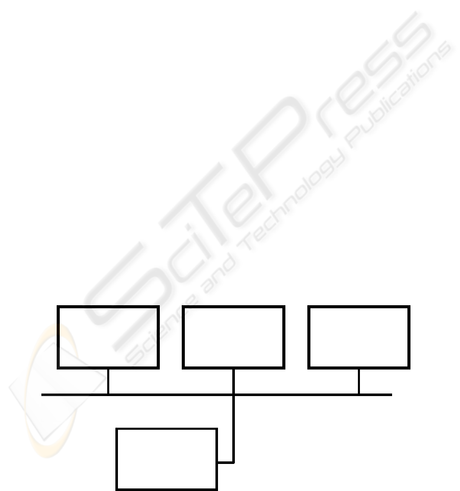
The diagram in Figure 1 shows pictorially the
architecture of the developed test-bed which consists
of four different stations. Each station plays a
specific role in the network and is loaded with
software that is appropriate for its role. The first
station is used for simulating the process to be
controlled as well as the sensors and the actuators of
the controlled plant. The second station simulates
the control functions that have already being using
the network. In fact, it generates network traffic
similar to the one that is expected to be produced by
the aggregated operation of all the other control
functions except the ones that we are going to
introduce. This traffic is exchanged with the first
station and is produced by a generator which can be
preset to send a number of packages the data size of
each package being determined statistically
according to the Poisson distribution.
When a master holds the token it may establish a
master-slave communication procedure with process
relevant devices, such as sensors and actuators for
exchanging data. Typically, the process relevant
devices are accessed through a slave network
interface whereas the distributed control algorithms
reside at master stations. The sampling and
activation of the sensors and actuators that are
related with the operation of the new control strategy
is carried out by the master station on which the new
control algorithm is running. Finally, the fourth
station is a monitoring station of the network
operation. By means of this station the various
timing parameters of the network can be measured
and the exchange of frames among the network
stations can be observed and recorded. Each station
is linked with the common data transmission
medium by the use of the Profibus interface card
PB-FM-1MS made by Softing (Softing, 2003) and
the necessary software on the host PC which
implements the levels 2 and 7 of the FMS protocol
of the Profibus standard. Data exchange between the
PC and the card takes place through a dual port
memory. The card configuration is carried out by the
Profibus window NT software which installs the
card driver and allows the user to set up the driver
parameters. The parameters are those that are related
with the network baud rate, the various network
parameters, such as token rotation time, slot time,
etc. In the first station where the plant dynamics are
simulated, the control systems simulation
environment of MATLAB is installed. It
communicates with custom-made application
Master Station 1
Process Simulation
Master Station 2
Aggregated Control
System
Master Station 3
New Controller
Profibus Bus
Monitoring system
Figure 1: The architecture of the test-bed
ICINCO 2005 - SIGNAL PROCESSING, SYSTEMS MODELING AND CONTROL
118
software in C which creates virtual objects of the
plant sensors and actuators and sends and receives
the output and input data to the plant model by
incorporating services of the application layer of the
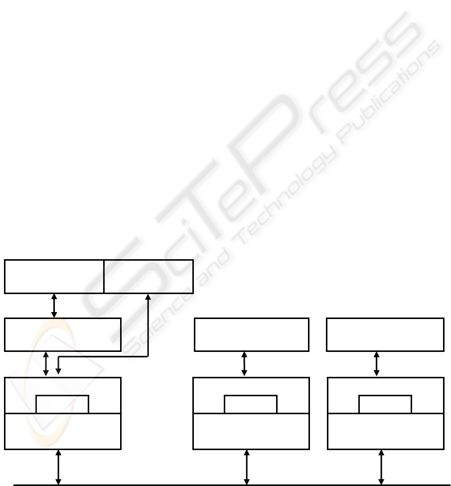
FMS protocol. In Figure 2 the architecture of the
installed software is pictorially depicted.
4 NETWORKED CONTROL OF A
CEMENT PLANT
Next, how the developed test-bed has been used to
evaluate the performance of the networked control
of two critical parameters of a cement plant will be
demonstrated. The considered control functions are
implemented on an existing Profibus network which
is supposed to be used for the control of other
variables of the same or other processes of a plant.
The insertion of these two new functions inflicts
additional traffic to the existing network and for this
reason both the influence of this traffic on the
stability and performance of the already running
functions has to be evaluated and the performance of
the new algorithms need also to be checked for
compliance with the control specifications. In fact,
one can assume that there are already known limits
for the existing control functions on their execution
deadlines. This will allow us to impose range limits
on the network tuning parameters the values of
which will be determined in a way that satisfies the
deadlines of the new network control functions.
In this work this assumption is made and the
performance of the considered plant is evaluated for
various network loads that the operation of the
existing control functions might inflict on the
network. First, a brief description of the control
problem of the cement plant is presented. The basic
process unit in the production of cement is the
cement milling circuit. Such units are fed with raw
material which after being ground is introduced into
a high efficiency classifier and separated into two
classes.
The tailings (refused part) are fed back into the
milling circuit while the finished product (accepted
part) exits the milling circuit. In the schematic
diagram of Figure 3 the milling circuit principle is
shown (Magni, 1999). The classification of the
material is driven by the rotational speed and by the
air flow rate of the classifier. The load in the milling
circuit depends on the input feed (fresh feed plus
tailings flow rate) and on the product flow rate that
depends in a non-linear way on the load in the
milling circuit and the hardness of the material.
There is a different upper limit of the load for each
hardness value which leads to circuit instability,
while keeping the load at a low level will result in
the fast wear of the mill internal equipment.
Figure 2: Software architecture of the Profibus stations
COMMUNICATION
SOFTWARE
NEW CONTROL
ALGORITHM
AGGREGATED
CONTROL
AGGREGATED
CONTROL
MATLAB
FMS Protocol
Drive
r
PB-FM-1MS card
FMS Protocol
Drive
r
PB-FM-1M card
FMS Protocol
Drive
r
PB-FM-1MS card
TESTBED EVALUATION OF NETWORKED CONTROL SYSTEMS
119
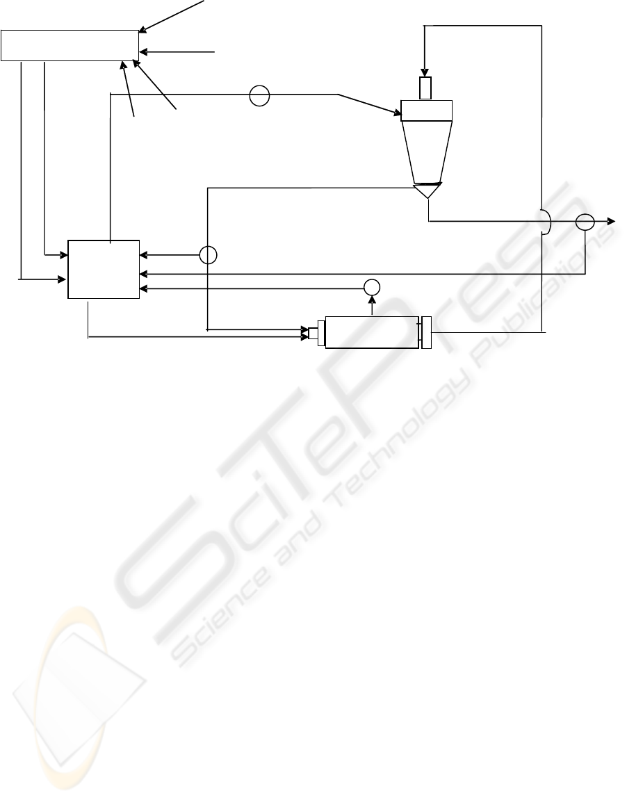
Figure 3: the milling circuit
A multivariable control technique, based on Linear
Quadratic Control (LQC) theory, has been
introduced (
Van Breusegen, 1996) to deal with the
instability problem. With this technique two
outputs, namely the product flow rate (y
r
) and the
load (z) are simultaneously controlled by using the
two available inputs, that is the feed flow rate (u)
and the classifier speed (v). For the implementation
of the LQC algorithm on the networked control
system the second master station was programmed
to perform this algorithm. In the first master station
the plant dynamics without the LQC control were
simulated in the MATLAB environment. During this
simulation the solution of the differential equations
is carried out at every sampling instant and then the
data of the controlled variables y
r
and z are read by
the second master, when this second master holds
the token. Also, within the same token holding time
the LQC computations are executed by using the
received data and the computed corrections for the
manipulated variables u and v are sent to the first
station where they are sampled in a similar way.
Then the token is passed to the third station which
generates data packages of sizes that are randomly
selected according to the Poisson distribution. These
packages are also read, enhanced by the data of the
cement plant and retransmitted over the network.
There are certain known deadlines for sending and
receiving data from the plant simulation, equal to the
sampling rate of each algorithm. To meet these
deadlines for a known network baud rate, the timing
parameter of the maximum token rotation time (trt)
and the slot time (tsl) have been preset. Also the
maximum retry limit (max_retry_limit) is set to
three. If, however these figures are not correct or
there are bursts of heavy traffic in the network,
sensor measurements and controlled variables
updates might not occur within the deadlines. This
might drive the controlled variables to deviations
from the desired transient and steady state
specifications.
By obtaining a recording of the variations
of the considered variables of y
r
and z over a horizon of
sampling instants at various traffic loads, possible
instabilities and deviations from the desired transient and
steady state specifications may be traced down. Then, new
tuning parameters may be tried.
5 TEST-BED EVALUATION
A number of experiments were conducted to show
the effect of different values of network timing
parameters
on the performance of the networked control
of the cement plant under varying network loads. The
study was conducted under three different loads, namely
for 5, 50 and 100 packages. The size of each package
varied from 0-510 bytes, randomly defined by the Poisson
distribution. The experiments were conducted for two sets
of trt and tsl values, that is for tsl=3.5msec and trt=10msec
and tsl=3.5msec and trt=2msec. In order to compare the
obtained test-bed results with the ideally expected
Speed
Product
Mill
Load Mill
Feeding
Multivariable
Control
Classifier
-
Supervisory Level
Tailings
ICINCO 2005 - SIGNAL PROCESSING, SYSTEMS MODELING AND CONTROL
120
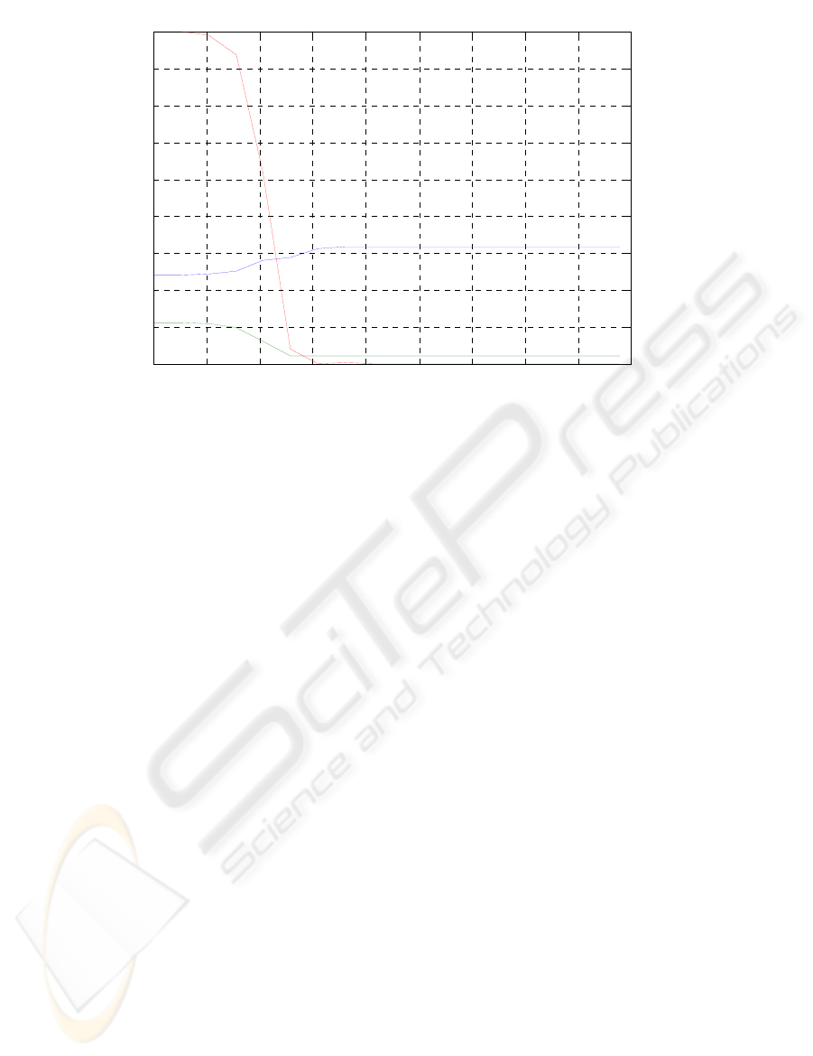
responses, the curves in Figure 4 are given. They have
been obtained from the MATLAB simulation of the
networked control of the cement plant.
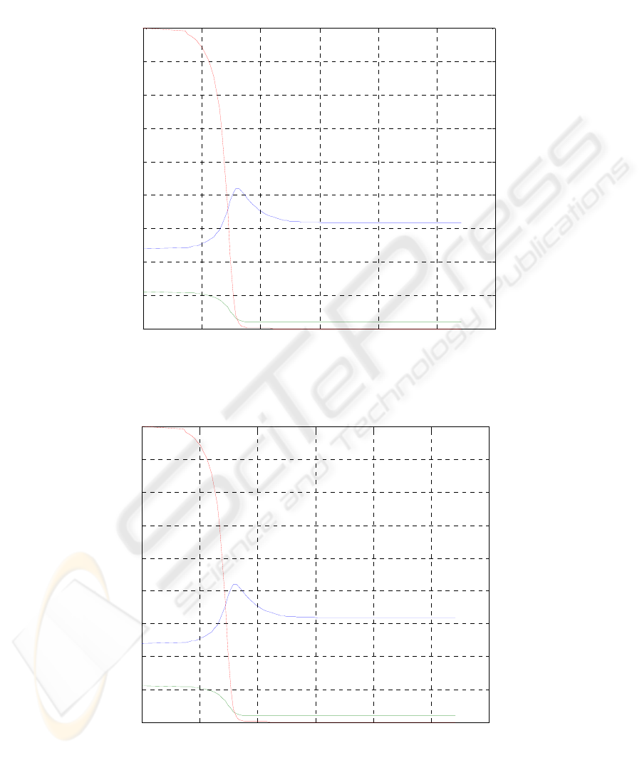
The test-bed
results for a network load of 50 frames, trt=10msec
and tsl=3.5msec are presented in Figure 5
. The results
for the same network load and tsl value but for trt=2msec
are presented in Figure 6.
0 1 2 3 4 5 6
0
50
100
150
200
250
300
350
400
450
time(sec)
metavlites
yf
yr
z
Figure 4: MATLAB Simulation of the LQC control of the cement plant
Figure 5: Plant response from the test-bed implementation of the LQC control of the cement plant for g=50, tsl=3.5msec
and trt=10msec
0 1 2 3 4 5 6
0
50
100
150
200
250
300
350
400
450
time(sec)
metavlites
yf
yr
z
TESTBED EVALUATION OF NETWORKED CONTROL SYSTEMS
121
0 2 4 6 8 10 12 14 16 18
0
50
100
150
200
250
300
350
400
450
time(sec)
metavlites
yf
yr
z
Figure 6: Plant response from the test-bed implementation of the LQC control of the cement plant for g=50, tsl=3.5msec
and trt=2msec
From the curves of Figures 4, 5 and 6 one can
conclude that the network delay has a small negative
influence on the settling time of the plant variables
when the trt =10msec. The settling time of the
product flow rate (y
r
) and the mill load (z) is around
3 and 1.8 time units respectively. These times are
very close to those predicted by the MATLAB
simulation. On the contrary, at trt=2msec the
difference from the simulation is significant, being
around 8 time units for the product flow and 5 time
units for the load. This is quite an expected behavior
as at small token rotation times the possibility of not
completing the sampling of the sensors and the
computation of the algorithm is quite high.
Therefore, according to the Profibus operation the
computations will be concluded by violating the trt
time. Consecutive violations added up over the time
will result to omit one or more computations at
certain sampling times, a condition that is known to
lead to a deterioration on the loop performance and
instability. However, problems of instability are not
monitored for the considered network load.
Although, one verifies practically what is most
likely to expect, the use of the test-bed can provide
to him additional quantitative information for the
responses of the networked control system Then, on
the basis of this information one can take decisions
for the trt and tsl values which can satisfy the
performance of the new control system without
affecting the performance of the already existing
control functions.
6 CONCLUSIONS
A test-bed with four master stations for evaluating
the performance of designed networked control
algorithms of physical processes has been developed
and its correct operation has been tested. The
network protocol implemented by the test-bed is the
FMS Profibus protocol. The conducted tests
involved the quantitative comparison of the
responses of the product flow rate and load of a
milling circuit of a cement plant to different network
data loads. They can be attributed to the use of the
network for other control operations in addition to
those of the cement plant. The comparison has
disclosed that as it was expected, the network delay
at small token rotation times influences the response
and especially the settling time. The use of the test-
bed can provide the necessary quantitative
information which will allow somebody to trade off
the network loading with more control functions at
the expense of performance degradation.
REFERENCES
DIN 19245, 1992. The Profibus standard part I and II,
translated from German, Profibus Nutzerorganisation
E.V.
EN 50170, 1996. General purpose field communication
system, CENELEC.
IEEE standard 802.4, 1985. Token passing bus access
method and physical layer specification.
ICINCO 2005 - SIGNAL PROCESSING, SYSTEMS MODELING AND CONTROL
122

Math Works, 1996. Matlab Control Systems Τoolbox,
User’s Guide, Version 5.
Magni, G. Bastin, and Vincent Wertz, 1999. Multivariable
Nonlinear Predictive Control of Cement Mills, IEEE
Transactions on Control Systems Technology. vol. 7,
no 4, pp. 502- 508.
Softing Gmb, 2003. Profiboard User’s manual.
Tovar E. and Vasques F., 1999a. Real-time Fieldbus
communications using Profibus networks, IEEE
Trans. Indust.,,Electron., vol.46, pp.1241-1251.
Tovar E. and Vasques F., 1999b. Cycle time properties of
the PROFIBUS timed-token protocol, Computer
Communications, vol. 22, pp. 1206-1216.
Van Breusegen V, Chen L., Bastin G., Wertz V.,
Werbrouck V., and de Pierpont C., 1996. An
industrial application of multivariable linear quadratic
control to a cement mill circuit, IEEE Trans. Ind.
Applicat., vol.32, pp. 670-677.
TESTBED EVALUATION OF NETWORKED CONTROL SYSTEMS
123
