
COLOURED PETRI NETS TO MODEL GEOGRAPHICAL
INTERLOCKING FOR RAILWAY
S. Ingram, M. A. Hossain* and S. Cox
Balfour Beatty Rail Technologies, Derby, DE1 2SA
*School of Informatics, Bradford University, Bradford, B07 1D7
Keywords: Coloured Petri Nets, geographical interlocking, mathematical modelling.
Abstract: Petri nets have been widely applied in different aspects of railway modelling and analysis. This paper
presents an insight into how coloured Petri nets can be used to model geographical interlocking. We start
with a generalisation of coloured Petri nets and follow with an overview of interlocking. In the main body
we present a generic unit model and demonstrate how it can be used to represent a simple junction,
comprising of three fundamental components; namely track, signal and point units.
1 INTRODUCTION
Ensuring the correct operation of control systems is
a complex task of vital importance, especially when
such systems control and monitor life-critical
operations. Owing to this fact, mathematical models
are increasingly being used to validate the design of
new safety critical systems, such as railway
interlockings (Hansen, 1998). Railway interlockings
are systems, which exist to prevent accidents in the
form of collisions and derailments, whilst at the
same time allowing maximum train movements.
This paper aims to demonstrate that using
coloured Petri Nets (CP-nets or CPNs) (Jensen,
1992, 1994a and 1997) offers a sound basis for
modelling geographical interlocking. CP-nets have
been applied in a wide range of application areas,
and many projects have been carried out in industry
(Jensen, 1997). Their ability to handle concurrency
makes them an ideal tool to model geographical
interlocking; i.e. an application where you have a
distributed control system made up of blocks known
as geographical units.
Petri nets (PTNs, Place Transition Nets) can be
represented as a bipartite graph composed of nodes,
which are places, transitions and arcs (Peterson,
1981). Places are represented by circles or ovals and
transitions by bars or rectangles. Places are
connected to transitions via arcs; arcs therefore
indicate the relationship between a place and a
transition. No two places or two transitions can be
linked directly. Places can be marked with one or
more tokens, which are drawn as dots. Tokens can
move between places as a result of an enabled
transition firing. A transition is enabled (i.e. ready to
fire) if all input places contain one or more tokens.
The firing of a transition will result in a token being
removed from each input place and a token being
deposited to each output place.
Petri nets have been extended in many ways such
as hierarchy, time and colour. The concept of CP-
nets is similar to that of ordinary PTNs; however,
CP-nets differ in that each token is equipped with an
attached data type known as a token colour (Jensen,
1992). Also, with CP-nets it is possible to make
hierarchical descriptions (i.e. a large model can be
obtained by combining a set of submodels)
(Janneck, and Esser, 2002). CP-nets provide a
framework for the construction and analysis of
models of distributed concurrent systems, such as
geographical interlockings.
This paper presents a generic unit model based
on CP-net notation and demonstrates how it can be
applied to a simple layout. Three components are
considered and used in the model; namely track,
signal and point units. Finally, a model of an
interlocking system is presented and discussed to
demonstrate the merits of Petri nets.
175
Ingram S., A. Hossain M. and Cox S. (2005).
COLOURED PETRI NETS TO MODEL GEOGRAPHICAL INTERLOCKING FOR RAILWAY.
In Proceedings of the Second International Conference on Informatics in Control, Automation and Robotics - Robotics and Automation, pages 175-180
DOI: 10.5220/0001176501750180
Copyright
c
SciTePress
2 INTERLOCKING SYSTEMS
As we mentioned earlier, the task of an interlocking
is primarily to prevent trains from colliding and
derailing, while at the same time allowing maximum
train movements. An interlocking receives requests
from the signaller (the person orchestrating train
movements along the network) and with the known
state of the trackside equipment (tracks states,
aspects states, etc) decides what operations can
safely be carried out by controlling signals and
points. The relationship between the signaller, the
interlocking and the trackside equipment is shown in
Figure 1.
Figure 1: Interlocking relationship diagram
Railway interlockings started off as purely
mechanical systems (Hall, 1992). A mechanical
system of “interlocking” leavers and locks was
directly connected to the signaller’s control panel
and would physically ensure that he could only
operate certain functions when it was safe to do so.
Mechanical interlocking has the advantage of being
robust, however they have proven to be difficult to
maintain and to alter. This lead to the development
of electromechanical interlocking (Relay based
Interlocking).
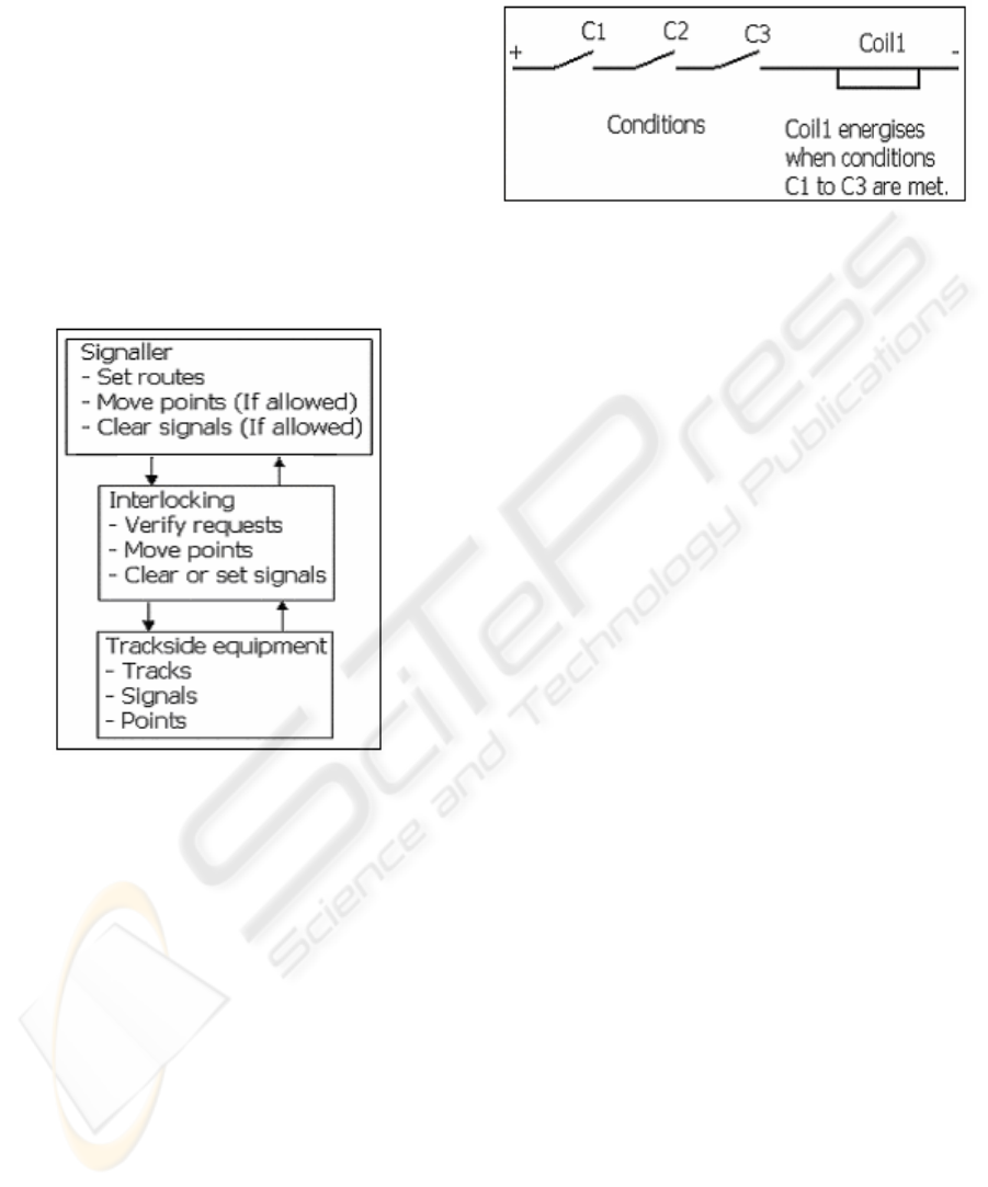
Relay based interlocking is used extensively in
UK (Hall, 1992). A relay interlocking consists of a
large number of fail-safe relays, and interlocking is
achieved through electrical circuits. An example of
electrical interlocking is shown in Figure 2. The
main advantage of relay interlocking is that the
technology is proven and dependable. However, the
main disadvantage is that they are very expensive to
build and maintain.
Figure 2: Electrical interlocking.
As modern technology became available, designers
were motivated to develop alternate methods based
on computer technology. Solid-state devices such as
the transistor are considered to be more reliable than
a relay (due to the lack of moving parts and contact
wear) and can be mass-produced cheaply. However,
a transistor cannot be constructed to be fail-safe in
the same way as a relay. If a transistor is to be used
in a fail-safe system, some additional safeguards
must be provided. Majority voting is one method
used to overcome this problem (Newing and Castles,
1988). It is considered that a single transistor may
not fail in a safe state; it is highly unlikely that two
would do so both at the same time. The decisions
made by two or three transistor circuits could be
compared and if they agree then the joint decision
can be considered to be “fail-safe”. The most
popular form of computer based interlocking is
Solid State interlocking (SSI) (Newing and Castles,
1988).
SSI is a multi computer based system developed
by British Rail in conjunction with Westinghouse
and GEC. SSI incorporates three independent
computers, each of which uses a large number of
transistor based circuits to decide what operations
trackside equipment can safely carry out (Newing
and Castles, 1988). Each interlocking computer
continuously monitors its own decisions, and those
of the other two. If a computer detects that it
disagrees with the other two, the computer shuts
down by blowing a security fuse. If the faulty
computer does not shut down, the other two act
together and shut it down themselves. This majority
voting helps to ensure that the system is reliable in
operation. Figure 3 depicts a simplified block
diagram of SSI; the three multiprocessor modules
(MPMs) are shown undergoing majority voting to
obtain a failsafe output.
ICINCO 2005 - ROBOTICS AND AUTOMATION
176
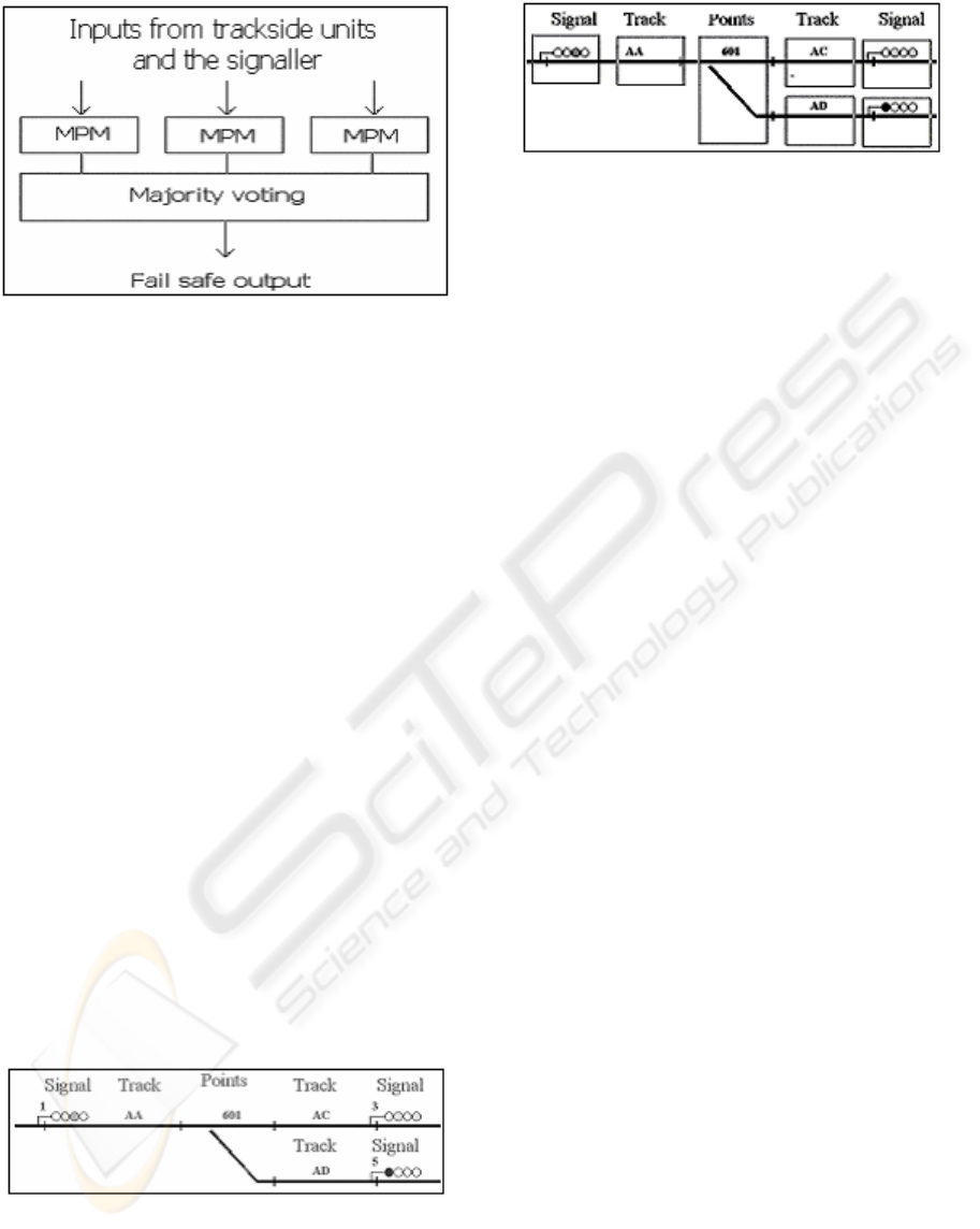
Figure 3: Simplified block diagram of SSI
Many relay based interlockings are of “free-
wired” design. This means that every circuit is
individually designed, installed and tested for the
particular application where it is to be used. This
process is very labour intensive and thus expensive.
Geographical interlocking systems however, are
made up of pre-designed and tested units that
represent each of the different pieces of signalling
equipment used to ensure the safe passage of trains.
All the interlocking functions required are built into
each geographical unit. They are connected together
via plug couplers to mimic the geographical layout
of the railway. Each unit has at least two and a
maximum of four connections. The connectors are
generally labelled Red, Blue, Yellow and Green
(Cox, 2003; WESTPACK, 1965). These connectors
allow electrical signals (or messages) to be passed
between units in order to set routes, move points and
clear signals. An example layout along with its
equivalent geographical representation is given in
figures four and five respectively.
The main advantage of geographical interlocking
is the ease of design and manufacture due to the use
of standard pre-defined units. Also if a unit fails
then the rest of the system can continue operating
while the failed unit is removed and a new unit of an
identical type is inserted.
Figure 4: Simple junction
Figure 5: Geographical representation
3 MODELLING APPROACH
Mathematically, a CP-net can be described as a
many tuple (Jensen, 1994b).
CPN = (∑, P, T, A, N, C, G, E, I) where:
(I) ∑ is a finite set of non-empty types, called
colour sets.
(II) P is a finite set of places.
(III) T is a finite set of transitions.
(IV) A is a finite set of arcs such that
• P∩T = P∩A = T∩A = ∅
(V) N is a node function. I is defined from A
into PxT∪TxP.
(VI) C is a colour function. It is defined from P
into ∑.
(VII) G is a guard function. It is defined from T
into expressions such that:
• ∀t∈T: [Type(G(t))=Bool^
Type(Var(G(t)))⊆∑].
(VIII) E is an arc expression function. It is
defined from A into expressions such that:
• ∀a∈A:[Type(E(a))=C(p(a))
MS^Type(
Var(E(a)))⊆∑] where p(a) is the place
of N(a).
(IX) I is an initialisation function. It is defined
from P into closed expressions such that:
* ∀p∈P:[Type(I(p))=C(p)
MS]
We mentioned earlier that geographical units
communicate using messages sent via couplers. It is
therefore essential that any model based on such a
scheme is message driven. From careful study of
(WESTPACK, 1965), we have derived a list of
typical geographical messages. These are shown in
table.1.
COLOURED PETRI NETS TO MODEL GEOGRAPHICAL INTERLOCKING FOR RAILWAY
177
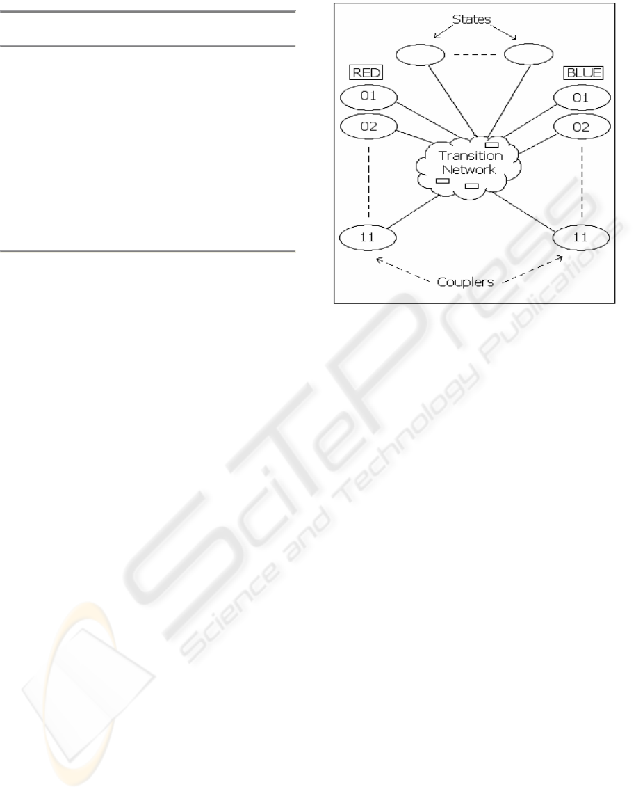
Table.1 Typical geographical messages
01 Call Route Request.
02 Call Route Reply.
03 Call Points Request.
04 Call Points Reply.
05 Lock Route Request.
06 Lock Route Reply.
07 Clear Signal Request.
08 Clear Signal Reply.
09 Release Route Request.
10 Track Status Request.
11 Track Status Reply.
We can define these messages in mathematical
notation as follows:
M = {01,02,03,04,05,06,07,08,09,10,11};
MES = {(R, B, Y)|R, B, Y∈M} ;
And in CP-net notation:
Color MES = with
R01|B01|Y01|G01|R02|B02|Y02|G02| R03|
B03|Y03|G03|R04|B04|Y04|G04|R05|B05|Y05|G05|
R06|B06|Y06|G06|
R07|B07|Y07|G07|R08|B08|Y08|G08|
R09|B09|Y09|G09|
R10|B10|Y10|G10|R11|B11|Y11|G11;
Each geographical unit consists of three common
elements; these are couplers, system states and
system actions. In our model, couplers and system
states are both modelled by CP-net places, and
actions are modelled by transition networks. Each
model has a minimum of two and a maximum of
four couplers. Geographical messages (see Table.1)
are received on either the red, blue, yellow or green
coupler; indicated by the presence of a token. The
reaction to the message depends on the type of
message received, the direction it is received in, and
the current state of the system. Having this
information now allows us to form a generic model
of what a unit should look like. This is shown in
Figure 6. Here we can see that the model has all the
necessary components, however, to apply the model,
we need to customise it for each unit by configuring
the transition networks according to some
interlocking specification. This is no trivial task and
is out of the scope of this paper.
Figure 6: Generic unit model
Places and tokens of the generic model are of data
type MES (which was defined earlier). The system
states vary from unit to unit (Cox, 2003); the
following is a brief overview of the track, signal and
point unit states.
3.1 Track unit
These are used to represent all plain line track
circuits. A track circuit is a section of track that
forms an electrical circuit capable of detecting the
absence of trains [8]. The states that require
modelling are.
(I) Route locking. This can be either locked or
free. This flag indicates whether or not a route
has been established across the unit. If a route
is requested and one is already established then
the unit replies with a request-failed message.
(II) Track state. This can be either clear or
occupied. This flag indicates whether or not
there is a train currently occupying the track. If
there is a train on the track when a message is
received then the unit replies with a request-
failed message.
3.2 Signal unit
These are used to represent all signal types. They
monitor the current state of the signal and control
what aspect is currently being displayed. Signal
ICINCO 2005 - ROBOTICS AND AUTOMATION
178
units also initiate all route setting between other
signals. The states that require modelling are:
(I) Signal state. This is the current state of the
signal (red or not red, i.e. green or yellow).
This flag indicates what aspect the signal unit
is currently displaying.
3.3 Point
These are used to represent a single end of points.
They monitor a single-track circuit and they also
control the movement of the point end. They may be
connected to up to three other units via red, blue and
yellow plug couplers. The states that require
modelling are:
(I) Route locking. (See track unit description).
(II) Track state. (See track unit description).
(III) Points normal. This can be either true or false.
If true then this indicates that the points are
currently in the normal (default) position.
(IV) Points reverse. This can also be true or false. If
true then this indicates that the points are
currently in the reverse position.
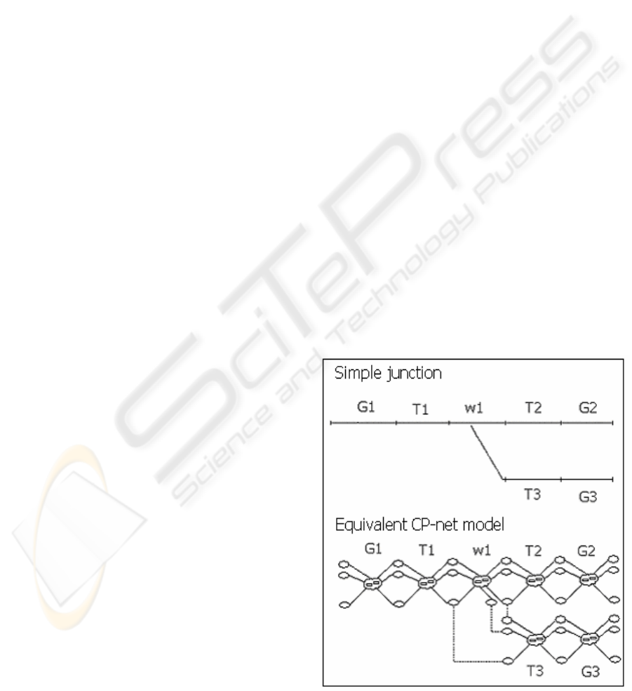
3.4 Modelling a junction
We shall now consider the layout shown in Fig.4.
Here we have a simple junction with only signals,
tracks and one set of points. Earlier we mentioned
that this layout could be represented in terms of
geographical units; this is depicted Fig.5. From
Fig.5 we can see that the junction is composed of
seven units. We therefore need seven customised
unit models to form this junction. Fig.7 shows the
simple junction and its CP-net model representation.
4 ROUTE CALLING EXAMPLE
For simplicity purposes, the junction will be
considered unidirectional and routes are set between
signals. A route can be set along the normal or
reverse path, i.e. from G1 to G2 or G1 to G3
respectively. The following is an example of route
calling from G1 to G3.
G1 issues a call route message to T1 with an
attached exit signal address. T1 examines its internal
states and if its track is occupied or a route is already
set then it sends a message back to G1 with a failed
tag attached. However, if T1’s track is clear and no
route is set then the same message is passed to the
points unit W1. W1 examines its internal states and
if it is in the normal position, it sends the message
on to T2. However, if it is in the reverse position, it
sends the message on to T3. T2 or T3 therefore
receive the message and examine their internal states
to see whether or not the message can be passed on.
It is worth noting at this point that if the track is
occupied or a route is set, then the message is passed
back to W1 with a failed tag attached. This failed
message will then be passed backwards until it
reaches the signal unit where it results in a request-
failed indication being issued to the signaller’s
panel. Assuming T2 received the message and its
track and route flags are clear, it then passes it on to
signal unit G2. G2 then checks the exit signal
address and compares it to its own. Discovering that
it does not match, it then passes the message back to
T2 with a failed tag attached. T2 passes the message
to W1. W1 then checks its internal state and if it is
in the normal position, it sends the message via the
yellow plug coupler to T3. T3 checks its states and
if they are clear, it passes the message to signal unit
G3. G3 checks the exit signal address and discovers
that it matches its own address, it then passes the
message back along the units to G1 with a request
grated tag. The other messages would travel along
the network in a similar manner.
Figure 7: Junction model
COLOURED PETRI NETS TO MODEL GEOGRAPHICAL INTERLOCKING FOR RAILWAY
179

5 CONCLUSION
This paper has presented an investigation into the
use of coloured Petri nets, which offers a basis for
the construction geographical interlocking unit
models. A layout of a junction was developed and
demonstrated the underlying concept of a generic
unit model. An example of message passing has
been provided which illustrated the working
principle of the developed model. This paper has
laid the foundations for further research into the
application CP-nets to modelling real-time
interlockings.
REFERENCES
Jensen, K. 1992. Coloured Petri Nets. Basic Concepts,
Analysis Methods and Practical Use, volume 1, Basic
Concepts of Monographs in Theoretical Computer
Science. Springer-Verlag, 1992.
Cox, S. 2003. Geographical Signalling System Overview.
September 2003. Balfour Beatty Rail Technologies
LTD.
Hall, S. 1992. BR Signalling Handbook, Ian Allen
Publishing.
Hansen, K. M. 1998. Modelling Railway Interlocking
Systems. Technical report, Department of Computer
Science, University of Denmark. November 26.
Janneck, J. W and Esser. R. (2002) High-order Petri net
modelling- techniques and applications. EECS
Department, University of California at Berkley and
Department of Computer Science, The University of
Adelaide, Australia.
Jensen, K. 1994a. Coloured Petri Nets. Basic Concepts,
Analysis Methods and Practical Use, volume 2, Basic
Concepts of Monographs in Theoretical Computer
Science. Springer-Verlag.
Jensen, K. 1994b. An Introduction to the theoretical
Aspects of Coloured Petri Nets. Inc de Bakker, J.W.,
de Roever, W.P., Rozenberg, G. (eds): A Decade of
Concurrency. LNCS 803. Berlin, Heidelberg, New
York: Springer-Verlang, pp. 230-272.
Jensen, K. 1997. Coloured Petri Nets. Basic Concepts,
Analysis Methods and Practical Use, volume 3, Basic
Concepts of Monographs in Theoretical Computer
Science. Springer-Verlag.
Newing, D. and Castles, M. 1988. SSI Overview Guide.
Railtrack PLC and Michael Hamly Associates LTD.
Peterson, J. L. 1981. Petri net theory and modelling of
systems, Prentice-Hall, Inc.
Westinghouse. The “WESTPACK” MK.IIIA. System of
Geographical Circu
itry. 1965.
ICINCO 2005 - ROBOTICS AND AUTOMATION
180
