THERMAL SPRAYING ROBOT KINEMATICS AND LASER
PATTERN CONTROL
D. Breen, E. Coyle and D.M.Kennedy
Faculty of Engineering, Dublin Institute of Technology, Dublin, Ireland
Keywords: Thermal spraying, kinematics, vision analysis, laser pattern control.
Abstract: The thermal spraying surface engineering industry relies on manual spraying and standard pre-programmed
robotic systems. This research presents the completed geometric forward and inverse kinematics solution
for a non standard articulated robotic manipulator which includes continuous 360
0
axis rotation for waist,
shoulder and elbow joints with a commercially available joint for tilt and pitch. The research also details the
use of Polytetrafluoroethylene (PTFE) electroless nickel slip rings and brushes for providing delivery of
power and data through the continuous rotation joints. The automatic analysis of distance and orientation
measurement via a pattern producing laser and camera system is being researched for suitability in the
thermal spraying process for automatic feedback and control of the robotic arm manipulator. The competed
technical and simulation design will provide for the automatic application of advanced surface coatings to
enhance wear, low friction and corrosion resistance properties to substrates via a thermal spraying process.
1 THERMAL SPRAYING
SURFACE COATING
1.1 Introduction
Surface coating via thermal spraying involves the
application of wear and corrosion resistant coatings
to various substrates and has been traditionally
carried out in the aerospace, power generation and
petrochemical industries (Air Products). However
improvements in the technology has resulted in
opening up of additional markets, in particular in the
biomedical and electronic coating industries. It is
further possible today to apply coatings to polymer-
based materials (England). Thermal spraying is a
generic term for a range of thermal spraying
technologies. There are four systems. These consist
of High Velocity Oxyfuel Spraying (HVOF), Plasma
spraying, Arc spraying and Flame spraying. Flame
spraying for example is used in the application of
corrosion resistance aluminium to off-shore oilrigs
(Air Products,
Richard Halldern) Another example
of surface coating is biocompatible hydroxylapatite
coating of prostheses, which are made of materials
such as titanium. This is achieved with the HVOF
system.
1.2 Powder Flame Spraying
The majority of components are sprayed manually or
via standard pre-programmed robot manipulators
and the development of an autonomous robot arm to
carry out the thermal spraying process will reduce
costs and health and safety risks.
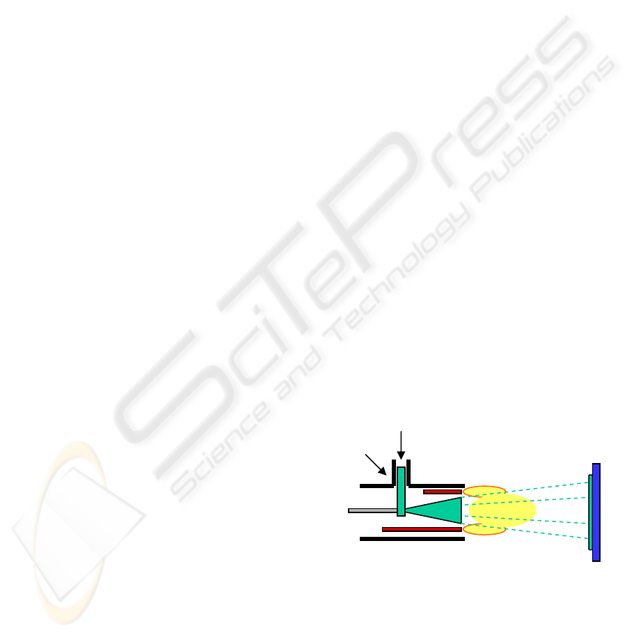
A schematic of the powder thermal-spraying
process is shown in Figure 1.
Coating
Powder
Flame
Spraying
Head
Burning
Gas
Sprayed
Material
Gas
Spray
Stream
Fuel
Figure 1: Powder thermal-spraying process
Prepared
Substrate
The coating process must occur in a very
precise manor to ensure quality control. Following
surface preparation, there can be up to three main
stages in applying a metallic coating to a substrate
and control of the position of the torch at each stage
is an important design and control parameter.
411
Breen D., Coyle E. and M. Kennedy D. (2005).
THERMAL SPRAYING ROBOT KINEMATICS AND LASER PATTERN CONTROL.
In Proceedings of the Second International Conference on Informatics in Control, Automation and Robotics - Robotics and Automation, pages 411-414
DOI: 10.5220/0001172504110414
Copyright
c
SciTePress
The three stages are pre-heating the substrate,
spraying the substrate with the coating material and
finally fusing the coating to the substrate. Other
processes only require pre treatment by shot
blasting. The coating and fusion process takes place
in a single step such as plasma or HVOF spraying.
2 ROBOT ARM KINEMATICS
2.1 Model of a five-axis articulated
robot arm with 360
0
joints.
While researching the type of robot manipulator
applicable to thermal spraying it became clear the
articulated type was preferable. It was also decided
to include the novel feature of continuous 360
0
rotation for the waist, shoulder and elbow joints
which provides advantages of maximising
workspace and improved flexibility. A 5 DOF
manipulator will also be specified, as spraying does
not require a roll axis thus reducing the cost of
additional joint actuator and control equipment.
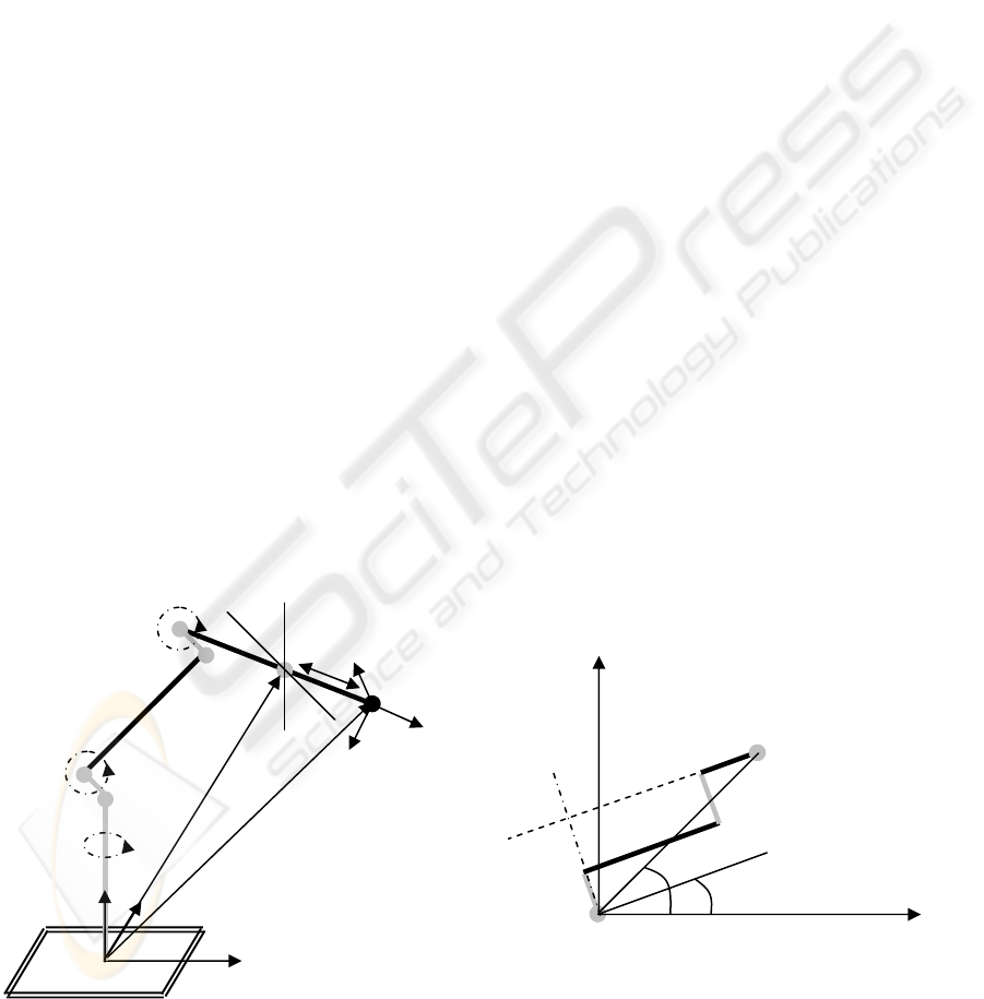
The model of a five-axis articulated robot arm
design, which has continuous 360
0
rotation waist, θ
1
shoulder, θ
2
and elbow, θ
3
joints is shown in Figure
2. A commercially available Omni-Wrist unit will
provide the pitch and yaw axis joints available from
Ross-Himes Designs. [Joints in grey, links in black].
Figure 2: Five axis robot arm model
2.2 Forward Kinematics
Using the Denavit and Hartenberg (Niku, 2000 et
al.) method and standard notation for developing the
robots forward kinematic arm matrix,
R
T
H
produces a
set of highly coupled, non linear equations in θ
1
, θ
2
,
θ
3
, θ
4,
and θ
5
for this particular robot design. The
Matlab
TM
symbolic toolbox was used to produce the
equations. To test these equations a model of the
robot arm was made using Lego
TM
and sample
solutions were tested successfully against the
physical model. As an example, using the vector of
angles in degrees [ -170 50 –45 20 –30 ] produces
the position and orientation matrix
n o a p
-0.42 -0.30 -0.86 3.46
-0.07 -0.93 0.36 -7.45
-0.91 0.21 0.37 24.56
0 0 0 1.00
2.3 Inverse Kinematics
To solve the inverse kinematics for this robot arm
with 360
0
continuous rotation joints the techniques
detailed in Sciavicco and Siciliano, 2000 and Niku,
2001 have been combined and modified as
necessary. The steps necessary to solve the inverse
kinematics are now detailed.
Step 1: From Figure 2 the wrist position vector is
given by p
w
= p – a
5
a.
Step 2: The second step is to determine the waist
angle θ
1
. This can be obtained by considering the
plan view of a general position angle θ
1
shown in
Figure 3.
Figure 3: Plan view at angle θ
1
The angle |AC| makes with the x
0
axis can be
determined from θ
AC
= Atan2(p
wy
,p
wx
). The length
|AB| = d
2
+ d
3
(fixed quantities) therefore ∠BAC can
be determined from trigonometry. The angle |AB|
p
wx
, p
wy
x
0
y
0
A
C
B
θ
1
θ
AC
Base
Z
0
y
0
x
0
Pitch
axis θ
4
Yaw
axis θ
5
Elbow, θ
3
o
a
n
Shoulder,
θ
2
Waist, θ
1
p
p
w
a5
ICINCO 2005 - ROBOTICS AND AUTOMATION
412

makes with the x
0
axis is ∠BAC + θ
AC
therefore θ
1
=
∠BAC + θ
AC
– 90 degrees. The angle θ
1
for any
point on the circle scribed by |AC| can be obtained
with this technique as can the angle on any plan
view circle within the robot arms workspace.
Step 3: Once θ
1
is determined the solution for angles
θ
2
and θ
3
become solutions for a simple two axis
robot arm in two dimensions as long as the p
wx
component is the length |BC| shown in Figure 3.
Step 4: Now that the waist, shoulder and elbow joint
angles have been identified a change of approach
will provide solutions for the pitch and tilt angles.
The forward arm matrix is made up of the
multiplication of six translation and rotation
matrices
R
T
H
= A
1
A
2
A
3
A
4
A
5
A
6
The product A
1
A
2
A
3
and its inverse can now be
calculated, therefore multiplying the given position
and orientation matrix by the inverse of A
1
A
2
A
3
will
provide a pan_tilt matrix, which is equal to A
4
A
5
A
6
.
A
6
is a constant known rotation and inspection of the
coefficients of A
4
A
5
A
6
provides solution equations
for θ
4
and θ
5
which are:
θ
4
= Atan2(pan_tilt(1,1), -1*pan_tilt(2,1))
θ
5
= Atan2(-1*pan_tilt(3,3),-1*pan_tilt(3,2)).
The solution outlined does not make use of the
360
0
continuous rotation capability of shoulder and
elbow joints as solutions will always place these
angles in the right half circle whose centre line is
along |AB| and containing the point C. However if
the shoulder and elbow joints make angles which
move point C into the opposite half of the circle then
a simple change will produce the alternative
solution; θ
1
= θ
AC
- ∠BAC – 90. The p
wx
component will be negative for this condition.
In a practical application requiring random
movement to different locations both solutions could
be tested and the one requiring the shorter travel
distance would be executed. The solution complying
with pitch and tilt limits also requires testing, as
does the elbow up and down options.
A Matlab
TM
function inv_axis_5.m has
been written which implements each of the steps
outlined for the first solution. However data to test
the code is difficult to generate. The data must be
within the operational workspace of the robot
manipulator and not cause singularities. Most robot
manipulators are pre-programmed and components
to be sprayed must be placed in exact location and
orientation, which is very time consuming. This
highlights one of the key areas for more advanced
research, that is the generation of trajectory data
using information from 3D transducers for the robot
to operate autonomously and to carry out requested
random movements efficiently. To test the code the
forward kinematic function axis_5.m was used to
generate position and orientation data as input data
to the inverse kinematics function.
Running the function using the previous
numerical example in section 2.2 where the input
angles are [ -170 50 –45 20 –30 ] provides solution
angles which are different [-170 20.7 45 -40.7 –30 ]
but with identical input and output position and
orientation arm matrices, highlighting the different
solutions outlined. The tilt and pan angles are within
range.
A significant advantage of continuous rotation
360
0
joints is the travel distance/time required. As an
example if the robot arm is in the home position and
a call is made for the shoulder joint to rotate 260
0
the
robot can move in the opposite direction by –100
0
in
a shorter time. If the same time is acceptable the
robot can move slower with less vibration. Safety is
a key issue and must be taken into consideration
with 360
0
continuous rotation calls as the torch may
hit the vertical joint.
Determining closed form inverse equations
produces a more computer efficient system than
alternative methods, which use the forward
kinematic equations, and iterative methods such as
Gaussian elimination (Niku).
2.4 Joint cabling
Joint cabling research for power and data is pointing
to the use of PTFE electroless nickel slip rings and
brushes. PTFE electroles nickel has the advantages
of low coefficient of friction, low wear and being a
good conductor. A prototype slip ring and brushes
test rig using electroless nickel coated copper
samples was set up and zero resistance was recorded
on the lowest resistance setting (200 Ω) of a
standard digital multimeter. Inclined plane tests
indicate a coefficient of friction for electroless nickel
on electroless nickel, which is 30% better than
copper on copper. PTFE electroless nickel should
provide better results than this. The slip ring and
brushes was videoed with the video signal passing
through the slip rings without any appreciable
reduction in quality.
3 LASER PATTERN CONTROL
Research is now concentrating on mapping
autonomously, complex 3D surfaces in the harsh
THERMAL SPRAYING ROBOT KINEMATICS AND LASER PATTERN CONTROL
413
environment of thermal spraying, for autonomous
robot manipulator control. This will reduce pre-
programming and set up times significantly.
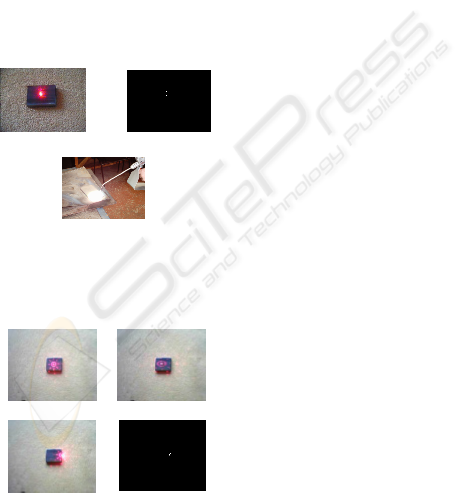
Initial depth measurement tests have been
carried out on the steel plate shown in Figure 4 with
a web camera and presentation laser. Image
processing and analysis has been carried out using
NeatVision (Whelan and Molloy, 2001), an open
source Java based image processing software
package and Matlab
TM
Image Processing Toolbox.
Figure 5 shows two white dots clearly separated,
correlating to the raising of the plate.
Further work on applying this technique and
measurement resolution obtainable in the harsh
environment of thermal spraying applications shown
in Figure 6 is ongoing.
Figure 4: Steel plate Figure 5: Depth
Figure 6: Harsh Thermal Spraying environment
Further research will also consider the use of
patterns produced by a laser when passed through a
diffraction grating for 3D surface mapping. As an
example the patterns shown in Figures 7 and 8,
provide information on depth (size of circle), flat
surface angle (elongation of circle) and sharp edges
(discontinuity of the circle).
Figure 7: Circle and Elongation
Figure 8: Discontinuity
Applying image subtraction tresholding erosion
dilation and thinning provides black and white
outline images of the circle, oval and semicircle for
further analysis. Image processing values were
chosen manually and the intended aim of the
research is for these values to be determined
automatically in the thermal spraying environment.
4 CONCLUSION
This paper has presented the forward and inverse
kinematics solution for an unusual 5-axis articulated
robot manipulator with 360
0
continuous rotation of
the waist, shoulder and elbow joints, and providing
an efficient method for determine joint angles from
given tool tip position and orientation. The
advantages of such a manipulator are also presented.
The paper has outlined the progress on developing
an efficient slip rings and brushes solution for
cabling through the continuous rotation joints.
The paper has also highlighted techniques being
pursued, which will be researched for their
effectiveness in the harsh environment of thermal
spraying. Solutions will transform time-consuming
pre-programmed thermal spraying operations to an
efficient autonomous operation.
REFERENCES
Air Products,. “Thermal Spraying”
http://www.airproducts.com/
England, G.,. “Thermal Spray Coatings on Carbon an
Glass Fiber Reinforced Polymers”
http://www.gordonengland.co.uk/
Matlab
TM
. http://www.mathworks.com
Niku, Saeed B., 2001. Introduction to Robotics Analysis,
Systems, Applications, Prentice Hall. New Jersey 1
st
edition.
Richard Halldern “Flame Spraying” TWI (2001)
http://www.twi.co.uk/j32k/protected/band_3/ksrdh001
.html
Ross-Himes Designs,.Omni-wrist
http://www.anthrobot.com/omni/detail.html
Sciavicco Lorenzo, Siciliano Bruno, 2000. Modeling and
Control of Robot Manipulators. Springer London 2
nd
edition.
Whelan, Paul F., Molloy, Derek, 2001. Machine Vision
Algorithms in Java Techniques and Implementation,
Springer. London 1
st
edition.
ICINCO 2005 - ROBOTICS AND AUTOMATION
414
