
A FAULT-TOLERANT DISTRIBUTED DATA FLOW
ARCHITECTURE FOR REAL-TIME DECENTRALIZED
CONTROL
Salvador Fallorina, Paul Thienphrapa, Rodrigo Luna, Vu Khuong,
Helen Boussalis, Charles Liu, Jane Dong, Khosrow Rad, Wing Ho
Department of Electrical & Computer Engineering, California State University, Los Angeles,
5151 State University Drive, Los Angeles, CA, USA
Keywords: Distributed data flow, pipelined task mapping, scheduling, fault-tolerance, real-time decentralized control.
Abstract: Complex control-oriented structures are inherentl
y multiple input, multiple output systems whose
complexities increase significantly with each additional parameter. When precision performance in both
space and time is required, these types of applications can be described as real-time systems that demand
substantial amounts of computational power in order to function properly. The failure of a subsystem can be
viewed as the extreme case of a non-real-time response, so the ability of a system to recognize and recover
from faults, and continue operating in at least some degraded mode, is of crucial importance. Furthermore,
the issue of fault-tolerance naturally arises because real-time control systems are often placed in mission-
critical contexts. Decentralized control techniques, in which multiple lower-order controllers replace a
monolithic controller, provide a framework for embedded parallel computing to facilitate the fault-tolerance
and high performance of a sophisticated control system.
This paper introduces a fault-tolerant concept to the handling of data flows in multiproc
essor environments
that are reminiscent of control systems. The design is described in detail and compared against a typical
master-slave configuration. A distributed data flow architecture embraces tolerance to processor failures
while satisfying real-time constraints, justifying its use over conventional methods. Both master-slave and
distributed data flow designs have been studied with regards to a physical control-intensive system; the
conclusions indicate a sound design and encourage the further division of computational responsibilities in
order to promote fault-tolerance in embedded control processing systems.
1 INTRODUCTION
Fault-tolerance may not be an overriding concern in
commodity electronics such as microwave ovens
and wristwatches; indeed, the development of
reliability features for such items may be an
inefficient venture. Fault-tolerance becomes an
essential characteristic of systems, however, when
the cost of failure is significant. The metrics used to
analyze this cost include safety and financial
concerns, so continuous uptime is a topic of interest.
Additionally the lifetimes of engineering systems are
limited by inherent manufacturing defects (Worden
& Barton, 2004), but fault-tolerance can provide for
graceful degradation, thereby creating a grace period
between fully operational and failed states during
which failure costs can be minimized.
The research described in this paper has been
conducted in t
he Structures, Pointing, and Control
Engineering (SPACE) Laboratory. The National
Aeronautics and Space Administration (NASA)
provided funding in 1994 to establish the SPACE
Laboratory at the California State University, Los
Angeles to study the control of complex structures.
A major goal of this ongoing project is to develop
control systems that exhibit fault-tolerance and real-
time response for the James Webb Space Telescope
(JWST), which is scheduled for deployment by
NASA in the year 2011. As the successor to the
currently-active Hubble Space Telescope, a major
specification of the JWST is the use of a larger
optical mirror to improve upon the quality of images
produced by the Hubble. Because there is an
apparent difficulty in transporting a single large
109
Fallorina S., Thienphrapa P., Luna R., Khuong V., Boussalis H., Liu C., Dong J., Rad K. and Ho W. (2005).
A FAULT-TOLERANT DISTRIBUTED DATA FLOW ARCHITECTURE FOR REAL-TIME DECENTRALIZED CONTROL.
In Proceedings of the Second International Conference on Informatics in Control, Automation and Robotics - Signal Processing, Systems Modeling and
Control, pages 109-115
DOI: 10.5220/0001172101090115
Copyright
c
SciTePress
mirror in current launch vehicles, the mirror of the
JWST will be divided into smaller segments whose
overall shape must be dynamically adjusted by an
active control system. However, the quality of
images collected by the telescope is a function of
shaping and pointing precision, among other duties.
Therefore the control processing system must
maintain a maximal level of fault-tolerance and high
performance to maximize the utility of the telescope.
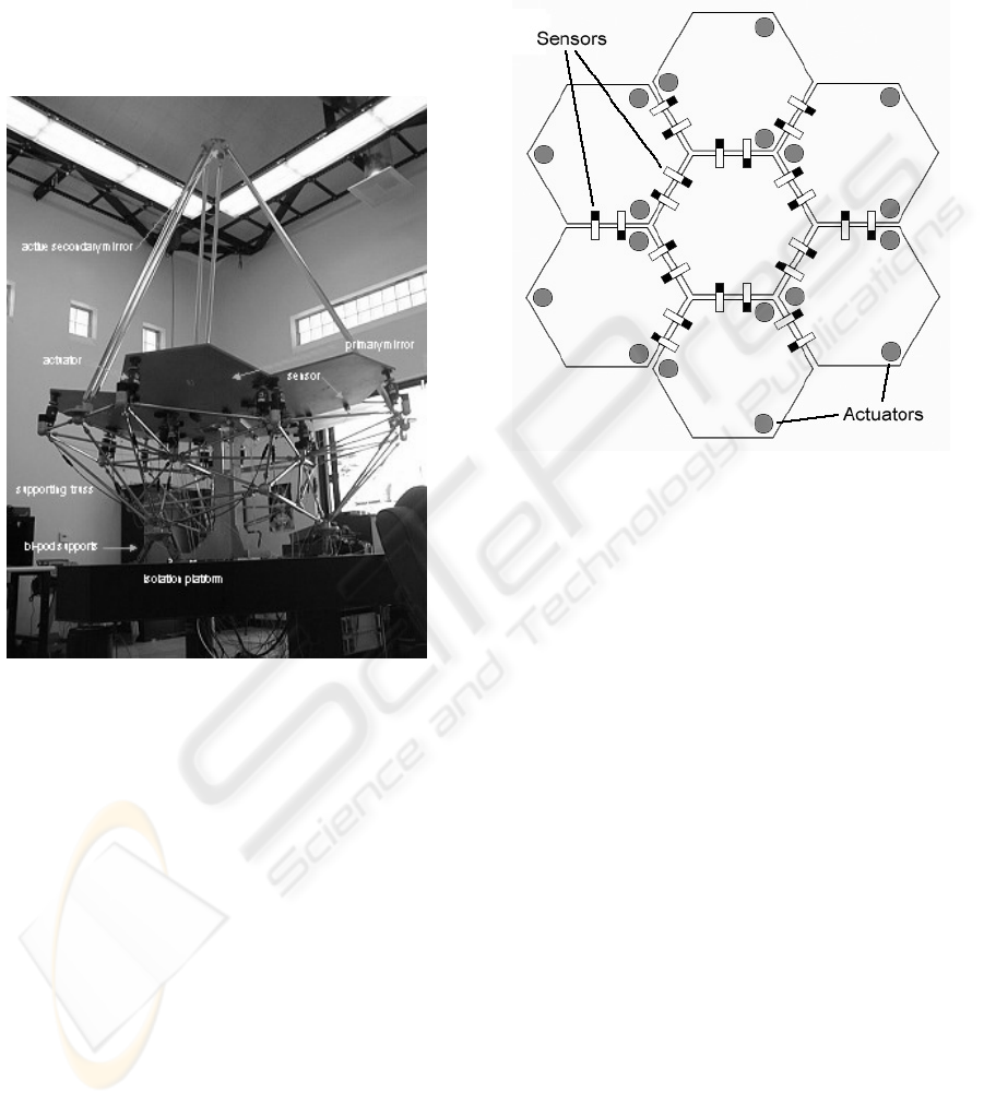
Figure 1: The SPACE testbed
Specifically, in an embedded multiprocessor
platform, the computing system must be able to
transparently perform processing tasks while
adjusting for the failure and recovery of processors.
In the event of processor failure, the computer
architecture must be reconfigured so that working
processors can assume any data handling
responsibilities previously held by failed processors.
In a converse manner, reconfiguration must be
performed when processors are recovered in order to
minimize the reliance of the system on any single
processor. By establishing mechanisms for fault-
tolerance, real-time performance can be realized
even when processor failures occur.
This paper is organized as follows. A description
of the SPACE testbed, on which research for this
project is conducted, is given in Section 2. Section 3
details the theoretical foundations for decentralized
control of the system. In Section 4, control
processing from the perspective of the computing
system is described. Section 5 presents the data flow
architectures under consideration, while Section 6
proposes a design that utilizes the novel data flow
mechanism to achieve processor fault-tolerance in
real-time decentralized control. Concluding remarks
are provided in Section 7 along with future plans.
Figure 2: SPACE testbed primary mirror
2 SYSTEM DESCRIPTION
2.1 Peripheral Structure
The SPACE testbed, pictured in Figure 1, resembles
a Cassegrain telescope with a 2.4m focal length. Its
performance is designed to emulate an actual space-
borne system (Stockman, 1997). As mentioned
above, the large optical mirror of the JWST will be
segmented so as to allow for conveyance via
contemporary launch vehicles. Figure 2 illustrates
the segmented mirror configuration present on the
SPACE testbed. A ring of six actively-controlled
hexagonal panels is arranged around a fixed central
panel. Three voice-coil linear actuators are mounted
to the underside of each panel, providing each with
three degrees of freedom. Twenty-four inductive
sensors are placed at the panel edges to provide
measurements of relative displacements and angles.
During control calculations these 24 sensors are
geometrically virtualized into 18 sensors, in
accordance with the arrangement of the actuators,
for implementation convenience. The actuators and
sensors are linked to the digital control processing
system respectively via digital-to-analog (DAC) and
analog-to-digital converters (ADC).
ICINCO 2005 - SIGNAL PROCESSING, SYSTEMS MODELING AND CONTROL
110
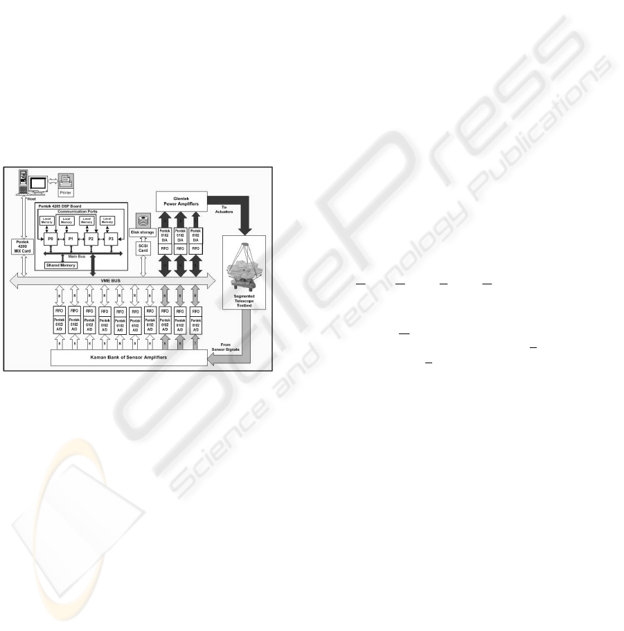
2.2 Embedded Computing System
The SPACE testbed processing system is configured
with four 32-bit TMS320C40 digital signal
processors. These processors feature a 40ns cycle
time and 30 MIPS/60 MFLOPS maximum ratings.
Each processor has 1 MB of local memory and
access to 1 MB of global memory (Figure 3). High-
speed, bidirectional, half-duplex communication
ports provide a maximum of 20 MB/s message
passing throughput amongst processors. Using a
VMEbus interface with a VIC64 chip acting as a bus
arbiter, each of the four processors has direct access
to the sensor input channels (ADC) and the actuator
output channels (DAC), giving rise to a myriad of
possible data flow configurations.
As an important note, the computing architecture
for the SPACE project is fixed. Therefore all
attempts at high performance and fault-tolerance
must be based on the existing hardware.
Figure 3: SPACE testbed computing system
2.3 Performance Requirements
To achieve the intended performance goals, any
algorithm designed for this control application must
complete computations in 0.8-1.6 ms per sample;
that is, using a sampling rate of 20-40 times the
system bandwidth of 30 Hz (Boussalis, 1994). This
specification, coupled with the structural complexity
of the telescope, attests to the real-time
computational requirements. Because sporadic
failure of processors to meet this time restriction is
of minor consequence, this application fits the soft
real-time systems category; however, prolonged
non-real-time performance will result in the
degradation of the quality of images collected by the
telescope.
3 DECENTRALIZED CONTROL
FOR THE TESTBED
Control of sizeable structures is an ongoing topic of
interest in space exploration programs. As described
previously, the SPACE testbed consists of a large
number of structural components whose behavior is
guided by a complement of sensors and actuators,
leading to mathematical models that involve
hundreds of states. Even after the application of
classical model reduction techniques, a centralized
control model of the telescope testbed has over 200
states complementing 18 virtual sensors and 18
actuators. Consequently, the design of control laws
based on conventional methodologies becomes
exceedingly unwieldy. Decentralized control then
becomes an increasingly attractive approach in
circumventing this difficulty concerning the
dimensionality problem.
Due to the complex nature of the SPACE
testbed, decentralized techniques are employed for
the development of simplified laws to accomplish
reflector shape control. The result is the physical
decentralization of the structure into six lower-order
subsystems.
The system equations of motion assume the form
dBuBKM
21
+=+
δδ
&&
. (1)
M refers to the mass matrix, and K the stiffness
matrix, while
δ
is a position coordinate vector, B
1
and B
2
are force amplitude matrices, u is a control-
input vector and
d is a disturbance vector. For
control purposes the following state-space
representation of the system is derived from (1).
Cxy
BuAxx
=
+
=
&
(2)
Decomposing the system (2) into six subsystems
according to the physical structure depicted in
Figure 2 yields (3) as follows.
iii
iii
i
iiiiiii
xCy
dBuBxAxAx
=
+++=
∑
=
21
6
1
&
(3)
The first term of (3),
iii
xAx
=
&
, (4)
is its isolated component, and
A FAULT-TOLERANT DISTRIBUTED DATA FLOW ARCHITECTURE FOR REAL-TIME DECENTRALIZED
CONTROL
111
[
]
T
i
T
ii
x
δδ
&
=
. (5)
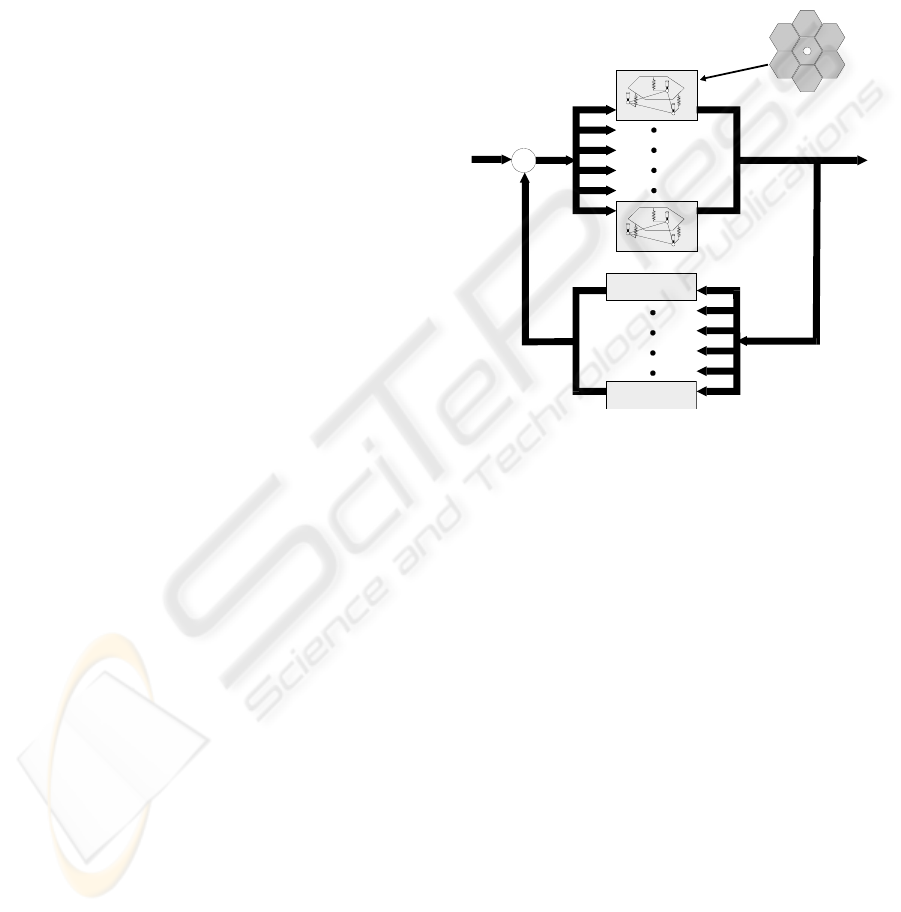
As shown in Figure 4, the system is naturally
decentralized by treating each of the six peripheral
segments of the primary mirror and its associated
supporting structure as an isolated subsystem. Each
decentralized controller can be of arbitrary type, as
hinted in the figure; an H
∞
controller is typically
used for testing. Each subsystem is identified by
three control inputs to the actuators and three control
outputs which are measured by the edge sensors.
Note that the definitions of inputs and outputs are
context-sensitive. The sensor signals are outputs of
the control system, but are inputs to the computing
system. A similar situation exists with regards to
actuator signals. Local control algorithms are
developed for each of the six isolated subsystems.
We consider discrete control algorithms. The
state-space form embodied in (2) is translated to the
discrete form shown in (6).
)()(
)()()1(
11
111
kxCky
kukxkx
nxrxnrx
mxnxmnxnxnnx
=
Ψ+Φ=+
(6)
This discrete state equation represents an n
th
-
order system with m inputs and r outputs (from a
computing systems perspective), where Ф is the
state transition matrix, x(k) is the state vector, u(k) is
the vector of sensor signals, and y(k) is the actuator
signal vector. In implementing decentralized control
for the testbed, a single 200
th
-order centralized
controller is replaced by six 12
th
-order local
controllers that run in parallel to maintain the precise
shape of the primary mirror. Such a replacement
reduces the computational complexity of the control
system, and exposes opportunities for both parallel
processing and fault-tolerance. The control
calculations for each of the six subsystems are given
below with n = 12, m = 3, and r = 3.
)()()(
)()()1(
keDkxCku
kekxkx
×+×=
×
Ψ
+×Φ=+
(7)
4 CONTROL PROCESS
DESCRIPTION
Given the nature of digital systems, control
computations are performed in discrete cycles, and
sensor readings are sampled accordingly. A control
cycle begins when processors read sensor signals
from the ADC and geometrically transform them
into virtual points that indicate the displacement and
positions of the panels. The next step consists of
calculating control commands for the six
subsystems. A single control task involves the
control calculations for a single subsystem, given in
(7). Resultant control signals are written to the DAC,
amplified, and sent to the actuators to properly
reposition the panels. As mentioned, these steps
must be executed continuously and within a
specified sampling period in order to ensure quality
shaping and system stability.
H
Controller
HController
Neural Network Control ler
2
∞
H Controller
H Controller
Neural Network Controller
2
∞
Σ
Figure 4: Decentralized control system block diagram
Sequential execution of control tasks using a
single processor is possible, but the disadvantages
that arise include extended execution time and lack
of fault-tolerance. Decentralized controllers present
opportunities for parallel execution during a control
cycle. Parallel processing is thus applied in order to
achieve fault-tolerance and real-time performance.
Based on our model of decentralized control, M = 6
tasks are executed in parallel among P = 4
processors in an iterative fashion.
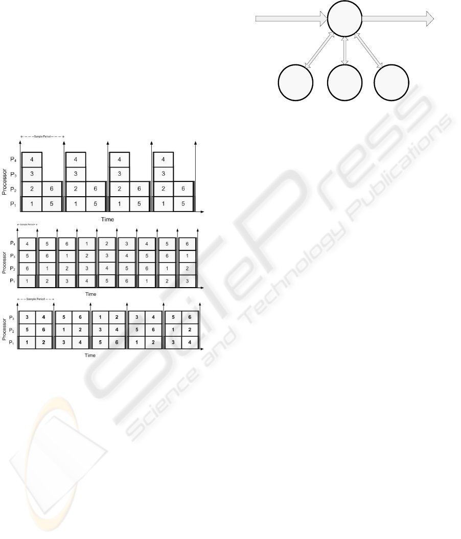
Whether they are scheduled for execution on
processors in a straightforward, pipelined (Fallorina,
2004, Thienphrapa, 2004), group-pipelined (Roberts,
2004) (see Figure 5), or other fashion, control tasks
must satisfy the following characteristics in order for
this application of decentralized control to work.
1. Each task is not further decomposable.
2. The computational complexities of all tasks are
identical.
3. Each task must complete a control cycle and
cannot be scheduled until its sample of sensor
signals is obtained.
4. There is no data dependency among the
computational tasks, so different tasks can be
ICINCO 2005 - SIGNAL PROCESSING, SYSTEMS MODELING AND CONTROL
112
processed in different control cycles in an
arbitrary order.
The computational dependence between the
subsystems is negligible. Thus the six panels of the
primary mirror do not need to cooperate with each
other to achieve precision shaping because local
controllers perform the alignment against a
calibrated parabolic reference. Note that for a
processor to process any number of tasks (Figure 5),
it must have access to the corresponding sample of
sensor signals, the current state vectors, and a means
of sending the actuator output signals to the DAC.
Therefore the design of fault-tolerant data flow
architectures is of utmost importance.
Figure 5: From top to bottom, straightforward, pipelined,
and group-pipelined task scheduling
5 DATA FLOW ARCHITECTURE
In order to ensure continuous control of the
telescope testbed, an efficient and reliable data flow
architecture needs to be in place that gives each
processor the full set of sensor data.
5.1 Master-slave Data Flow System
One conventional approach structures the flow of
data in a master-slave configuration (Figure 6). In
this method, only one processor, the master, handles
all the data inputs and outputs. The master processor
reads all data from the ADC first-in, first-out (FIFO)
buffers and passes them to each of the slave
processors. Once each processor finishes the control
computations, the results are passed back and
gathered by the master processor, which then
proceeds to send the control commands to the plant.
Figure 6: Master-slave data flow
Master
P
1
Slave
P
3
Slave
P
4
Slave
P
2
Input:
Sensor Data
Output:
Control Commands
This arrangement is simple and straightforward,
but
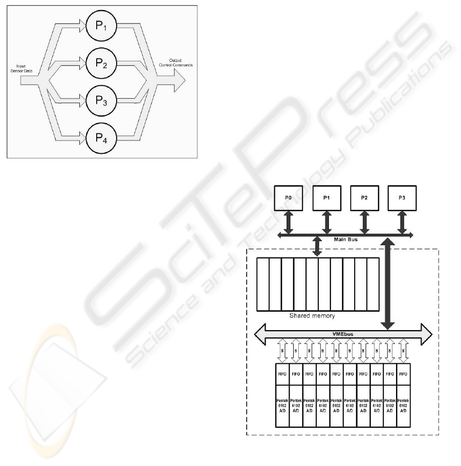
5.2 Distributed Data Flow System
The proposed distributed data flow architecture
5.3 Comparison
This distributed scheme is more compatible with the
servation, what warrants
discussion of the master-slave architecture is its
widespread use in situations where failure is not a
relies on a single processor. The system can be
made to tolerate any slave processor failure, but in
the event the master processor fails, then the entire
computing system fails.
detailed here describes the development of a
symmetric computer architecture where all
processors operate identically. In this distributed
data flow architecture (Figure 7), all processing
nodes are capable of handling any input and output
of data. In other words, each processor can read
sensor signals from the ADC buffers independent of
other processors, then perform its subset of the
decentralized control calculations (this subset, i.e.
task(s), is assigned based on the task mapping
mechanism in use (Fallorina, 2004, Thienphrapa,
2004, Roberts, 2004)). Upon completing its
calculations, each processor can then independently
send the results to the plant to command the
appropriate actuators.
concept of decentralized control and facilitates fault-
tolerance by removing the reliance of the system on
any single processor. If one or more processors fail
or recover from failure, the architecture is able to
accommodate for these events and resume normal
operations transparently. This is the distinguishing
advantage of the distributed system over the master-
slave configuration. Failure of the master processor
would lead to immediate failure of an entire master-
slave computing system.
In light of this ob
A FAULT-TOLERANT DISTRIBUTED DATA FLOW ARCHITECTURE FOR REAL-TIME DECENTRALIZED
CONTROL
113
pre
high performance, fault-
considered, they were
discounted due to the fixed, specialized nature of the
sible due to rigid power constraints.
Oth
N
hitecture to
m, various
challenges arise due to its physically centralized data
destructive-read FIFO buffers on different ADC
the ADC
boa
co e
veral bottlenecks in the architecture that do not
have redundancies. However, an abstraction is
created that allows for the design of fault tolerance
ssing concern (e.g. desktop computers), as well
as its ease of implementation. Specifically, the
distributed data flow architecture introduces
synchronization issues; processors must be
synchronized within a control cycle in order for task
scheduling to transpire correctly. Correctly
implementing this mechanism with synchronization
is nontrivial. Such matters can play a role in the
development costs, development time, and reliability
of the end product.
Figure 7: Distributed data flow
5.4 Limitations
Although several works in
tolerant computing were
SPACE testbed.
For instance, hardware and software redundancy
described in the literature (Reinhardt, 2000, Khan
2001) are not fea
er approaches assume workstation environments
(Baratloo, 1995, DasGupta, 1999) that do not exhibit
real-time performance. Due to hardware limitations,
reconfigurable circuits (Blanton, 1998) and
proactive fault detection (Siewiorek, 2004) cannot
be used. Fortunately, the control process is
straightforward and does not require sophisticated
task mapping (Choudhary, 1994).
6 DATA FLOW DESIG
In applying the distributed data flow arc
the SPACE testbed computing syste
bus (Figure 8). Firstly, given the system architecture
and hardware capabilities and limitations, the
implementation of this design method requires more
communication. Sensor data is located in
boards (Figure 8). Therefore, any data read by a
processor is removed from the corresponding buffer
space. If such data is required by the other
processors, point-to-point communication between
the processors will be necessary. Another
practicality is that VMEbus accesses must be time-
shared amongst processors. In addition, task
mapping becomes complicated when integrated with
pipelined task scheduling techniques (Fallorina,
2004, Thienphrapa, 2004, Roberts, 2004).
To implement this distributed data flow
architecture, each processor reads a subset of the
total data and distributes the data amongst each
other. This is achieved by configuring
rds to send interrupt signals to assigned
processors which read data from the interrupt
source. Each time a processor takes data from the
ADC FIFO buffers, it writes that data to shared
memory where any other node can access it. This
step is necessary because the full set of sensor
samples is generally required to process control
commands for any subsystem task. Future work will
address the effects of using only a subset of these
samples. In the end, all of the data is made equally
available to any processor, producing the logical
effect of distributed data flow.
Figure 8: Distributed data flow on the SPACE testbed
The architecture of the system board and the
VMEbus connection to the processors are not
nducive to perfect fault tolerance. There ar
se
ICINCO 2005 - SIGNAL PROCESSING, SYSTEMS MODELING AND CONTROL
114

that
dered ideas
inc
han
ue to
failure. One facet of fault-tolerance provides for a
f
to prepare for ultimate failure. More central to this
processor
bec
fault tolerance via test and reconfiguration’, Proc.
any.
bility of Large Scale Systems.
Ph.D. dissertation, New Mexico State University.
d Distributed Systems, vol.
Das ards
Fal al. 2004, ‘A generic pipelined task
Kha 001, ‘Fault-tolerant embedded
Rei ransient fault
Rob
group-
Sie
g at Carnegie Mellon
Sto
Time When Galaxies Were
Thi nt
Wo erview of
bypasses hardware limitations. Furthermore, an
implementation will demonstrate proof-of-concept
that the proposed solution does indeed support fault-
tolerant real-time decentralized control.
Although fault detection is a rich area of interest
in its own right, it is briefly discussed here as it
pertains to the SPACE testbed. The shared memory,
message passing, and interprocessor interrupt
resources can be used to construct various fault-
tolerance mechanisms. Already consi
lude using watchdog, neighbor, and ad hoc
detection methods to indicate the state of processors.
Reconfiguration for faults and recovery must be
efficient in real-time systems. Pipelined task
mapping performs this reconfiguration at the control
task level by dynamically assigning tasks based on
the working state of processors. At the data flow
level, working processors can assume the data
dling duties of failed processors in a state
machine-like fashion. That is, the sensor and
actuator channels that processors access will be
determined by the quantity and identities of the
processors that are failed. The mechanical attribute
of such an approach will foster efficiency.
7 SUMMARY & FUTURE WORK
Costly and mission-critical systems must exhibit
fault-tolerance in order to minimize loss d
grace period between fully functional and
non unctional states during which steps can be taken
project, however, is the uptime. It is desirable for a
space telescope to smoothly continue operation
despite the failure of processors on a multiprocessor
platform, which is a single-event upset in nature and
is a likely occurrence given the operating
environment. With tolerance for processor failure
enabled, a telescope can perform its scientific and
logistical duties with minimal downtime.
The distributed data flow architecture proposed
here has been conceived for fault-tolerant, real-time
decentralized control of a segmented reflector
telescope testbed. In contrast with a master-slave
configuration that has already been implemented,
this approach does not rely on a single
ause the data input-output can be handled by any
processor. This arrangement facilitates continuous
system operation despite any processor failure.
Future work includes completion of the distributed
data flow architecture, detection and reconfiguration.
Various fault detection and reconfiguration schemes
will be tested and analyzed in addition to issues of
sensor, actuator, and signal converter failure.
ACKNOWLEDGEMENTS
This work was supported by NASA under Grant
URC NCC 4158. Special thanks go to all the faculty
and students associated with the SPACE Laboratory.
REFERENCES
Baratloo, A. et al. 1995, ‘CALYPSO: a novel software
system for fault-tolerant parallel processing on
distributed platforms’, Proc. IEEE HPDC, PC, VA.
Blanton, R., Goldstein, S., & Schmidt, H. 1998, ‘Tunable
FTCS, Munich, Germ
Boussalis, H. 1979, Sta
Boussalis, H. 1994, ‘Decentralization of large space-borne
telescopes’, Proc. SPIE Symposium on Astronomical
Telescopes.
Choudhary, A. et al. 1994, ‘Optimal processor assignment
for a class of pipelined computations’, IEEE
Transactions on Parallel an
5, no. 4, pp. 439-445.
Gupta, B. et al. 1999, ‘Generalized approach tow
the fault diagnosis in any arbitrarily connected
network’, Proc. HiPC, Calcutta, India.
lorina, S. et
scheduling algorithm for fault-tolerant decentralized
control of a segmented telescope testbed’, Proc. ASME
DETC/CIE, Salt Lake City, UT.
n, G., & Wee, S. 2
computer system-on-chip for endoscope control’,
Proc. ISIC, Singapore.
nhardt, S. & Mukherjee, S. 2000, ‘T
detection via simultaneous multithreading’, Proc.
ISCA, Vancouver, BC.
erts, J. et al. 2004, ‘Efficient real-time parallel signal
processing for decentralized control using
pipelined scheduling’, Proc. ISNG, Las Vegas, NV.
wiorek, D. et al. 2004, ‘Experimental research in
dependable computin
University’, Proc. WCC, Toulouse, France.
ckman, H. et al. 1997, The Next Generation Space
Telescope: Visiting a
Young, The Association of Universities for Research
in Astronomy, Baltimore, MD.
enphrapa, P. et al. 2004, ‘A generalized fault-tolera
pipelined task scheduling for decentralized control of
large segmented systems’, Proc. CCCT, Austin, TX.
rden, K. & Dulieu-Barton, J.M. 2004, ‘An ov
intelligent fault detection in systems and structures’,
Structural Health Monitoring, vol. 3, no. 1, pp. 85-98.
A FAULT-TOLERANT DISTRIBUTED DATA FLOW ARCHITECTURE FOR REAL-TIME DECENTRALIZED
CONTROL
115
