
USE OF THE COG REPRESENTATION TO CONTROL A ROBOT
WITH ACCELERATION FEEDBACK
Frédéric Colas, Eric Dumetz, Pierre-Jean Barre
Technological Research Team – ERT CEMODYNE, ENSAM, 8 avenue Louis XIV, 59046 Lille Cedex, France
Jean-Yves Dieulot
Ecole Polytechnique Universitaire de Lille, LAGIS, UMR 8146 CNRS, Cité Scientifique,
59651 Villeneuve d’Ascq Cedex, France
Keywords: Causal Ordering Graph, Industrial robot, Acceleration feedback, Jerk, Vibration control.
Abstract: A controller using acceleration feedback has been applied to a flexible robot for which the position and
velocity of the load are not measured. It is shown by using the Causal Ordering Graph (COG), that the
motor can be controlled by using acceleration feedback and that it allows an exact tracking of the motor
position, irrespective of the non-linear flexibilities of the axis and of the measurement disturbances. This
easy-to-tune algorithm, in which main control parameters are the modal masses of the motor and load part
and only consists of a positive acceleration feedback plus a PD controller, has been validated on an
industrial 3-axis robot.
1 INTRODUCTION
The demands for smaller operation times, low-
energy consumption and lower robot costs are the
main motivations for the use of lightweight high-
speed robots. However, high speed and accelerations
supported by such flexible robots lead to undesirable
vibrations. Since vibrations deteriorate the
equipment and affect the precision of the positioning
device, their damping should be considered as a
prerequisite to any further increase of performances.
As will be explained below, the combination of this
underdamped behaviour and the lack of measures on
the end-point makes it impossible for the current
industrial control structures to perform rapid and
robust closed-loop dynamics.
Obtaining accurate control-oriented models of
complicated flexible structures is not an easy task.
Whereas finite element method (FEM) allows the
different modes of deformation of a structure to be
understood, they are not suitable for control
purposes. A simpler model can be obtained when
decomposing the structure in a set of rigid bodies
linked by spring elements using Assumed Modes
Methods (AMM). Meirovich have proven to be able
to represent the dynamic structure of a CNC axis
drive (Meirovich, 1994). In such a complex structure
as a flexible Cartesian robot, it has been found
experimentally that the springs’ stiffness exhibit
large variations whereas modal masses remain
nearly constant. Moreover, it is impossible to
measure the load position and velocity in the
industrial context, since the cost of measurement
devices (e.g. a laser or a camera) is prohibitive. As a
consequence, only the motor part is controlled in
closed loop whereas the load is controlled in open-
loop, and this fundamental aspect is not often
accounted for in the literature (Béarée, 2004). It has
been shown (Béarée, 2004) that the combination of
low damping and the lack of measures on the load
results in poor control performances. As an
alternative to load position measurements, the use of
an accelerometer mounted on the effector’s end can
provide additional information at a reasonable price.
Since it is impossible in practice to derive the
velocity and position of the load from an integration
of the acceleration signal owing to the important
measurement noise, the acceleration feedback
should be directly embedded in the controller.
Acceleration feedback has been be expressed in
the framework of optimal control (Luo and Saridis,
1985) for which a compensation of non-linear terms
enforces the tracking error to converge
asymptotically to zero. This method, however, needs
to measure the torques at the motor shafts and the
25
Colas F., Dumetz E., Barre P. and Dieulot J. (2005).
USE OF THE COG REPRESENTATION TO CONTROL A ROBOT WITH ACCELERATION FEEDBACK.
In Proceedings of the Second International Conference on Informatics in Control, Automation and Robotics, pages 25-31
DOI: 10.5220/0001171900250031
Copyright
c
SciTePress
joint accelerations, and is not easily applicable in an
industrial context, where such complete and accurate
measurement is not available. Indeed, the tuning and
the practical implementation of this algorithm (Mc
Inroy and Saridis, 1990) meets many difficulties
such as the obtaining of angular accelerations and
torque measurements which require further
computations or approximations. It has been shown
experimentally that an increase of the sampling
frequency or the feedback gains leads to instability.
In summary, there have been few experimental
results actually based on the measured acceleration
information.
In this paper, the same acceleration feedback
algorithm of (Luo and Saridis, 1985) is deduced by
using the Causal Ordering Graph (COG introduced
by Hautier, 2004) on a robot modelled by a two
mass model with a spring with lumped stiffness
parameters. The COGs consist in a graphical
language for describing the dynamics of physical
systems and provide general methodology to
determine their control structures.
Contrary to Luo and Saridis algorithm, the
developed controller just needs the value of the
modal masses and is thus easier to tune. Two figure
cases will be tackled, corresponding to the industrial
context: the tracking of a reference trajectory of the
motor, and the tracking of a reference trajectory of
the load for which the motor reference motion is
computed off-line.
The paper is organized as follows: the modelling
approach of the robot is described in the first part.
The acceleration feedback algorithms are developed
next section. Finally, real-time validations are
presented for an industrial pick-and-place robot.
2 A LUMPED MASS-SPRING
MODEL OF AN INDUSTRIAL
ROBOT
The robot which is considered in this study is an
industrial Cartesian robot, which exhibits an average
cycle time of 3 s, a mass of 750kg and accelerations
up to 4m.s
-2
. The robot cycle time is a key parameter
in the overall process optimisation. The vibrations
due to the robot flexibilities (in particular that of the
vertical axis) are quite underdamped, and become
critical when exceeding more than 2mm (or 0.3mm
on the motor reference trajectory), which restrains
the performances and limits the cycle time.
In this part, it will be recalled how classical
modelling methods allow to design a control-
oriented model which respects the physics of the
structure of such a flexible robot and allows the
damping of vibrations. A presentation of such
methods can be found in more details in (Meirovich,
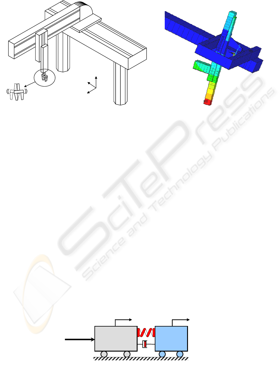
Figure 1: Identification of the main deformation mode (Horizontal motion X axis: Bending of Z) with ANSYS
Z
Y
X
1
x
2
x
2
m
1
m
U
k
a
1
x
2
x
2
m
1
m
U
k
a
Figure 2: Two-mass-spring model of a Cartesian robot (X axis)
ICINCO 2005 - INTELLIGENT CONTROL SYSTEMS AND OPTIMIZATION
26

1994), (Ellis, 2000).
The Finite Elements Method is a classical tool
which enables an accurate modelling of the
dynamical behaviour of a flexible system, using a
polynomial approximation of the deformations of
elements such as beams, plates, etc... Figure 1
shows the first deformation mode due to the bending
of the vertical Z-axis during the horizontal motion of
the robot. The evolution of the other deformation
modes during the motion of the robot in its working
space is not intuitive.
Whereas this method allows the behaviour of the
robot to be understood, its complexity prevents its
use for control purposes. An alternative method to
the modelling of small deformation consists of
decomposing the structure in a set of rigid bodies
which are linked by spring elements using the
method of Assumed Modes. A model with lumped
parameters for which the stiffness of the spring
depends on the position of the load mass in the
working space allows the first deformation modes to
be represented (Meirovich, 1994). This study will be
limited to the modelling and control of the first
deformation mode, i.e. projection of the bending of
the vertical axis on the horizontal plane during the
motion of the X axis. The dynamical model of the
motion can be represented by a two-mass model
with a spring of variable stiffness.
Modal analysis can be carried experimentally
using an impulse response obtained when exciting
the effector’s end with an impact hammer (Barre,
96). The signal is recorded using a spectrum
analyser. The variation of the modal parameters for
an horizontal displacement (axis X) is moderate but
becomes very important because of torsional
coupling when both the axis X and Y are moving.
All these parameters are lumped through the value
of the Z position. According to Figure 2, the
equations of model are:
(
)
(
)
11 2 1 2 1
mx k x x a x x u=−+−+
&& & &
(1)
()
(
)
22 1 2 1 2
mx k x x a x x=−+−
&& & &
(2)
()
02
kk gy=+ (3)
where u is the driving effort, x
1
and x
2
are
respectively the positions of the motor and the load
for the horizontal X axis, y
2
is the position of the
load for the transverse Y axis, m
1
and m
2
are
respectively the modal masses of the motor and the
load part, k is the modal stiffness. Experimental
results show that g(y
2
)=a.y
2
+b.
Consider an horizontal displacement, for which
y
2
-y
20
=α(x
2
-x
20
). The stiffness k is now a linear
function of the load position x
2
, with k=k
0
+aα(x
2
-
x
20
)+b+ay
20
.
The frequency of the main deformation mode
and the corresponding damping ratio are given:
1
2
n
eq
k
F
M
π
=
,
2
eq
A
kM
ς
=
,
12
111
eq
M
mm
=+
(4)
3 ACCELERATION FEEDBACK
As discussed previously, the motor part can be
controlled in closed-loop whereas the load is
controlled in open-loop. Two control methods can
be employed, depending on the specifications that
are required by the user. As an example, one may
want to improve the cycle time while others want to
reduce the load’s vibrations to an acceptable level.
3.1 Tracking of the Motor Reference
Position
Since the concept of causality is important in the
comprehension of the physical phenomena, we used
a tool called the Causal Ordering Graph and
introduced by Hautier (Hautier, 2004). It allows us
to represent a system with elementary objects
defined using energetic considerations. When an
object does not store any information, the causality
will be defined as external and the output will be
derived directly as a function of the input. The
relation (R) is then called rigid:
If an object stores information, the causality is
internal and the output is a function of the energetic
state of the system. In this case, the relation (R) is
called causal, both the time and initial state are the
implicit inputs:
When the model of the process is established, the
control structure is deduced by inversion of the
COG. This model being made up of causal and rigid
relations, two different solutions for the inversion
result:
In a Rigid Relation, a bijective relation C
determines a control law using direct causal
inversion.
R
y
u
R
y
u
USE OF THE COG REPRESENTATION TO CONTROL A ROBOT WITH ACCELERATION FEEDBACK
27
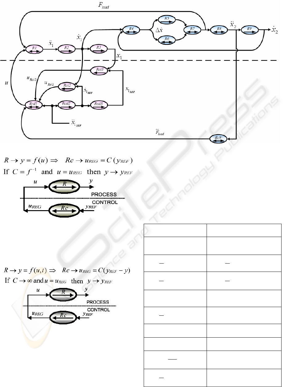
In a Causal Relation, time acts implicitly so that
the accumulation effect induces an initial value and
the relation is not bijective any more. Thus, the
tuning value u
reg
is elaborated while taking into
account, at any moment, the value of y according to
its reference y
ref
. This inversion principle is nothing
but the measurement feedback principle.
Applying these rules, we obtain the COG
representation of the Motor Control which is shown
in Figure 3. The different relations are summarized
in Table 1. The overall control u is obtained by using
the model inversion principle and choosing C
2
and
C
3
as simple gain k
1
and k
2
:
(
)
(
)
22 11 1 1 1 2 1 1
MES REF REF MES REF MES
umx mx kx x kx x=++−+−
&& && & &
(5)
It allows a perfect tracking of the motor
irrespective of the non-linear flexibilities of the axis
and of the measurement disturbances. One can
recognize the simplified version of the acceleration
feedback algorithm of (Luo and Saridis, 1985). This
is the main advantage to use the COG formalism.
Indeed, the motor control algorithm is derived easily
by using this tool.
Table 1: Relations of the COG representation of the Motor
Control
Two-Mass-Spring Model Motor Control
111
()
load
RmxutF→=−
&&
1
11 2 1 3 1
()
REF
ci reg
load
Rut
mx F C x C x
→=
++∆+∆
%
&& &
()
211
d
Rxx
dt
→=
&&&
()
211
R
EF REF
cd
d
Rxx
dt
→=
&&&
()
311
d
R
xx
dt
→=
&
()
311
R
EF REF
cd
d
R
xx
dt
→=
&
412
R
xx x→∆ = −
&& &
()
22 211
REG REF MES
ci ci
Ru Cxx→= −
&&
()
5 spring
d
R
Fkx
dt
→=∆
&
()
33 311
REG REF MES
ci ci
Ru Cxx→= −
6 viscous
R
Fax→=∆
&
922
MES
c load
R
Fmx→=
%
&&
7 load spring viscous
RF F F→= +
82
2
load
F
Rx
m
→=
&&
()
922
d
Rxx
dt
→=
&&&
Fi
g
ure 3: COG re
p
resentation of the Motor Control
ICINCO 2005 - INTELLIGENT CONTROL SYSTEMS AND OPTIMIZATION
28
3.2 Load’s Vibrations control
The former method of control consists of enforcing
the motor to follow a prescribed trajectory.
Conventional controllers for Cartesian robot use a
reference trajectory for the motor position, which
does not guarantee performances for the dynamics of
the load. An alternative method consists of defining
a reference trajectory for the load (e.g. a trajectory
with no vibrations). The corresponding motor
reference trajectory is determined using model
inversion by differentiating relation (2):
()
(
)
() ()
1021 221
222
022 222
REF REF REF REF REF
REF REF
R
EF REF REF REF REF
ax k g x x g x x x
ax m x
kgx x gx x x
⎡⎤
′
=− + −
⎡⎤
⎣⎦
⎣⎦
++
⎡⎤⎡ ⎤
′
++ +
⎣⎦⎣ ⎦
&& & &
&& &&&
&&
(6)
Where x
2
REF
is the desired load trajectory
Equation (6) underlines that the third derivative
of the load position (the jerk) should be continuous
in order to avoid peaks on the motor acceleration
(and thus on the control). Indeed, the jerk value is
known to be a key tuning parameter (Barre, 2004).
4 EXPERIMENTAL VALIDATION
The main objective of the validation part is to show
that the acceleration feedback allows the cycle time
to be increased and the vibrations on the motor and
the load to be reduced. The experimental section is
organized as follows: the robot is moving diagonally
and results are compared for the tracking of a
prescribed motor trajectory, and for a load reference
trajectory with small and high jerk.
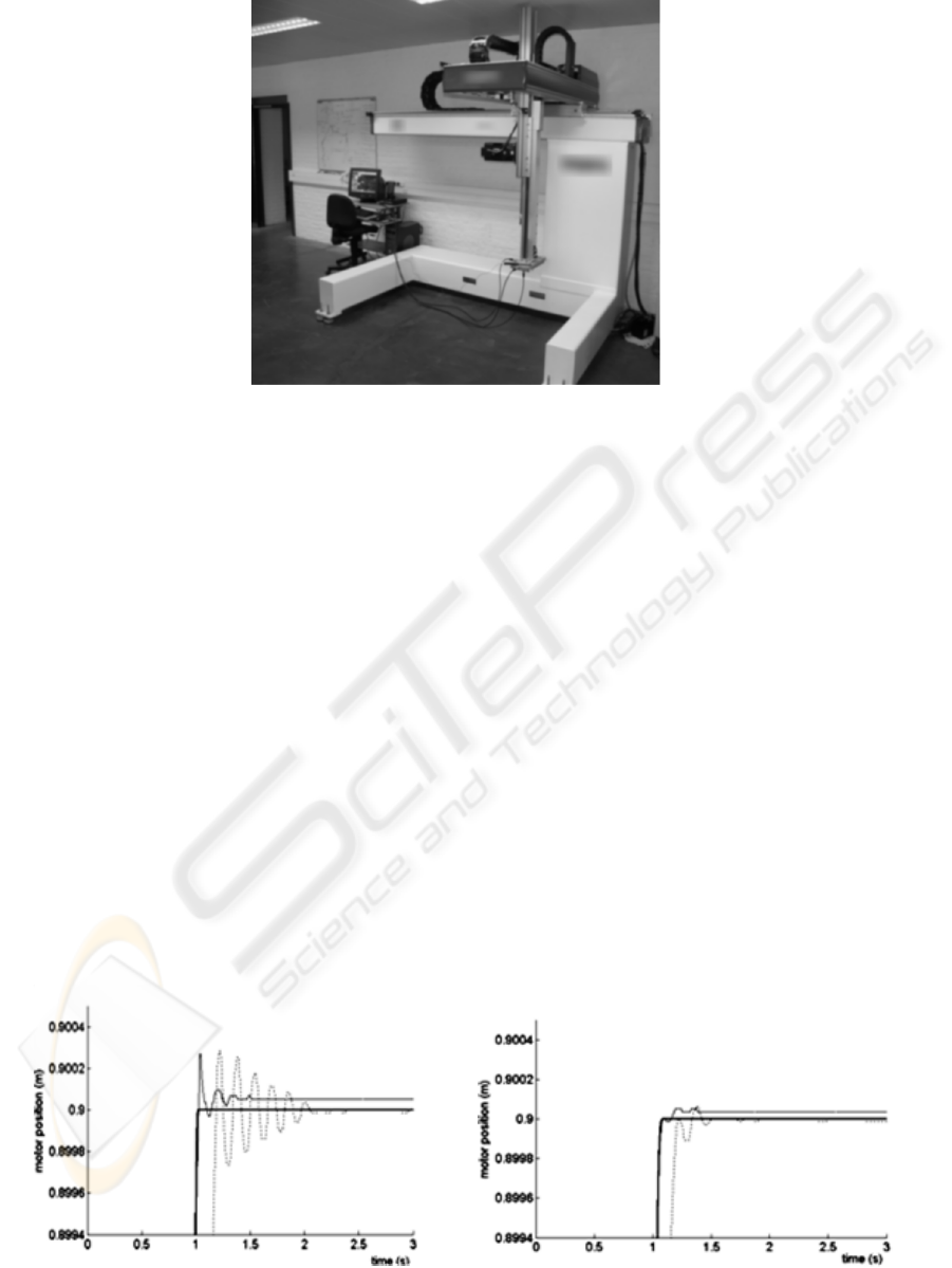
4.1 Material
The experimental validations are carried out on a
Cartesian 3-axis robot (figure 4). It was equipped
with a real-time “dSPACE 1103” control card. The
available measurements on the motor part come
from the actuator encoders of axis and an
Figure 4: Overview of the test-setup prototype (stroke [mm]: X-1000 Y-400 Z-800, maximum speed: 120m/min,
maximum acceleration: 4m.s
-2
).
Figure 5: Diagonal displacement, motor position - a)
-3
500 ms ,
J
e
=
b)
-3
50 ms ,
J
e
=
Strong Full Line: Reference
Trajectory, Full line: Acc. Feedback, Dotted: Industrial loop.
a)
b)
USE OF THE COG REPRESENTATION TO CONTROL A ROBOT WITH ACCELERATION FEEDBACK
29
accelerometer located on the effector’s end gives the
load acceleration. A laser sensor (measuring
distance: 50mm / measuring range: 20mm) directly
gives the load position and is only used for
experimental verification.
The validations are undertaken for a
displacement y
2
-y
20
=α(x
2
-x
20
), where x
2
varies from
x
20
=0 to x
2
=900mm as before, and y
2
varies from
y
20
=0 to y
2
=400mm, with a height z=315mm. The
transverse Y-axis is controlled with a classical PI
controller, it has been checked that the actual
trajectory is nearly a straight line.
4.2 Tracking of a Motor Position
Reference Trajectory
The reference trajectory profile is a classical jerk-
limited bang-bang, i.e. the acceleration exhibits a
trapezoidal profile. The average modal masses taken
in the model and used for control (5) and simulations
are m
1
=350kg and m
2
=46kg (mean value), according
to that determined experimentally. The stiffness in
equations (1-3), according to the X-axis, is:
()
00
022 2
kk a x x bay
α
=+ − ++ (7)
where k
0
=1.27 10
5
N.m, α=0.444, a=-1.56 10
5
N. The
error on the stiffness correlation ranges from ±15%,
the mean uncertainties on modal masses are about
±25%. k varies from 1.27 10
5
N.m to 0.66 10
5
N.m,
i.e. about 100% during the whole course. In the case
considered, there exists an optimal value of the jerk
which limits the amplitude of vibrations (Béarée,
2004) (Barre, 2004), which is of 50ms
-3
.
One can see that the combination of the
acceleration feedback and an appropriate jerk allows
the rise time to be greatly improved while vibrations
almost vanish (Figure 5). In any case, the
acceleration feedback outperforms the conventional
loop (tuned at its best). The rise time is about 1.05s
when the robot is controlled with acceleration
feedback with a high jerk value, (1.15s with a jerk of
50ms
-3
) versus respectively 1.25s and 1.39s for the
conventional feedback with high and low jerk
values. The tracking performances of the
acceleration feedback algorithm allow to
compensate for the lag resulting from the use of a
low jerk value.
In theory, residual oscillations on the motor
position should not occur. Unperfect trajectory
following and oscillations can be due to non-linear
effects in axis coupling that where not taken into
account in the model, Coulomb friction effects and
effective variations of the modal masses. The results
on the load position show that high-amplitude
oscillations still occur whereas the cycle time is
improved.
4.3 Tracking of a Load Position
Reference Trajectory
An appropriate acceleration profile of the load is
now considered, for which the jerk is limited either
to 50ms
-3
or to 500ms
-3
. The trajectory will be
chosen to be the same as the reference trajectory of
the motor which was chosen in the previous
validation scheme. The motor reference trajectory is
thus derived using equation (6).
One can find that the damping is quite better
with acceleration feedback (one significant peak),
while the cycle time (obtaining of a near-steady state
value) reduces to 1s versus 1.15s for the
conventional algorithm. The results with an
appropriate jerk show that the load can be damped
very quickly (the oscillations are not even visible by
the operator, and with an amplitude under 0.2mm)
with far better performances than the conventional
algorithms (with or without jerk). Simulation results
are good enough, considering that the true variation
of modal masses was not taken into account.
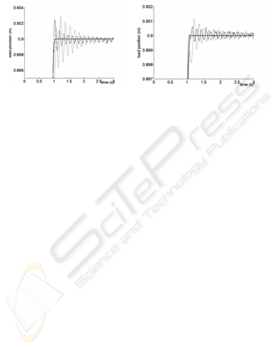
a)
b)
Figure 6: Diagonal displacement, load position - a)
-3
500 ms ,
J
e
=
b)
-3
50 ms ,
J
e
=
Strong Full Line: Reference
Trajectory, Full line: Acc. Feedback, Dotted: Industrial loop
ICINCO 2005 - INTELLIGENT CONTROL SYSTEMS AND OPTIMIZATION
30

Figure 6 shows the robustness of the acceleration
feedback with respect to modelling errors and
nonlinearities (considering that modelling errors are
quite important, more than 20% for each parameter).
The conventional controller is unable to compensate
the variations of stiffness as shown in figure 7
(oscillations are up to 3mm which is far too much for
the application considered). Oscillations are quite
underdamped with a low jerk. Nevertheless, the
gain on the cycle time is quite important (more than
0.15s), the amplitude of the oscillations do not
exceed ±0.5mm, which is quite satisfactory for our
application.
5 CONCLUSION
An acceleration feedback algorithm has been
determined by using the COG methodology. It
allows, in theory, an exact tracking of the motor
position. Moreover, model inversion allows an
appropriate motor reference to be derived to control
the load. This algorithm has been successfully
applied to an Industrial Robot which dynamics is
modelled by a two-mass spring with lumped
parameters and in the case of the load’s vibration
control, the Acceleration Feedback Controller nearly
eliminates the vibrations on the load. This may allow
to increase the performances of such manipulators
and to improve greatly the cycle time.
REFERENCES
Hautier, J.P., Barre, P.J., 2004. The Causal Ordering
Graph, a tool for system modelling and control law
synthesis. Studies in informatics and Control Journal,
Vol. 13 n°4,p265-283.
Barre, P.J., Hautier, J.P., Charley, J., June 24-27, 1996.
The use of modal analysis to improve the axis control.
Fourth International Congress on Sound and
Vibration, St Petersburg, Russia, pp. 1531-1538.
Barre, P.-J., Bearee, R., Borne, P., Dumetz, E., In press,
2004. Influence of a Jerk Controlled Movement Law
on the Vibratory Behaviour of High-Dynamics
Systems. Journal of Intelligent and Robotic Systems.
Béarée, R., Barre, P.J., Bloch, S., 2004. Influence of high
feed rate machine tool control parameters on the
contouring accuracy. Journal of Intelligent and
Robotic Systems, 40, p 321-342.
Luo, G., Saridis, G., 1985. L-Q design of PID controllers
for robot arms. IEEE Journal of Robotics and
Automation, 1, p152 – 159.
Meirovich, L., 1994. Principles and Techniques of
Vibrations, Prentice Hall.
Ellis, G., 2000. Control system design guide, Academic
press, Boston, 2
nd
edition.
McInroy, J.E., Saridis, G., 1990. Acceleration and torque
feedback for robotic control: experimental results. J
Robotic Systems, 7, p 813-832.
USE OF THE COG REPRESENTATION TO CONTROL A ROBOT WITH ACCELERATION FEEDBACK
31
