
GENERAL ENGINEERING DATA MODEL IN SPECIAL PURPOSE
MACHINE ENGINEERING
Zhiliang Qi, Christian Sch
¨
afer
Software and Systems Engineering for Production Automation (CR/APA3), Robert Bosch GmbH
Robert-Bosch-Strasse 2, D-71701 Schwieberdingen, Germany
Peter Klemm
Institute for Control Engineering of Machine Tools and Manufacturing Units, University Stuttgart
Seidenstrasse 36, D-70174 Stuttgart, Germany
Keywords:
Modeling, Mechatronic systems, Optimization.
Abstract:
A main problem in todays engineering of special purpose machines is the reuse and the consistency of en-
gineering data across the whole development process. This paper presents an approach how to manage and
share data in the entire development process in the field of special purpose machine engineering. The first
part gives a short overview of the current problems by using software tools in engineering and the engineering
requirements. In the second part the current data models used in special purpose machine engineering are
analyzed. The third part provides the General Engineering Data Model (GED) as a new concept to share and
reuse the engineering data from each engineering phase and to improve the development activity. At the end
this paper gives also an evaluation on benefits and contribution of this GED.
1 INTRODUCTION
The fast evolution of software technology in recent
years offers new potential for engineering. Engineer-
ing is done more efficient and with better results using
engineering tools. This reduces the development cost
by 15-30% and shortens the production cycle time by
30-60%. The product quality is improved by 20-50%
(Rembold et al., 1994).
Yet this approach concentrates only on applying
and improving stand-alone engineering tools. Today
the focus has moved from stand-alone engineering
tools towards a coupled net of engineering tools. In
a next step to improve the engineering with respect to
time, cost and quality, interdisciplinary data exchange
is the key issue (Westk
¨
amper, 2002; EPLAN, 2005;
VDI, 2003).
In the field of special purpose machine engineer-
ing numerous and various stand-alone software tools
are used in the machine development. Each software
tool provides support for a special engineering phase
e.g. planning, design, application programming, man-
ufacturing etc. In many engineering phases even more
than one software tool is applied (Starke, 2001; Cio-
coiu et al., 2001).
Each software tool resolves one or more engineer-
ing tasks based on the necessary information. The
engineering result of one phase is needed as input-
information to resolve engineering tasks in other
phases (Welp et al., 2001). On the other hand, a set of
information is accessed from several tasks. The avail-
ability of these information is important to improve
the engineering process flow. Therefore the data ex-
change between the engineering phases is one of the
main challenges (Germer et al., 2001).
Product development in engineering is a contin-
uous work and conventionally divided into several
phases which are executed one after the other or paral-
lel in some case. Today most of the software tools and
their data models are independent from each other.
Each of them presents itself as an isolated application
and is used within one engineering tool. The same
machine is modelled in each software tool and inter-
preted differently (Keil and Schmidt, 2001). They
have also their individual document format to store
data. All of this makes the data management and
data exchange between the engineering phases diffi-
cult (Germer et al., 2001).
1.1 Requirements on engineering
data model
The engineering tasks become more complex from
day to day. To improve the engineering quality and to
shorten the developing time, software tools and their
data models face the new requirements from engineer-
348
Qi Z., Schäfer C. and Klemm P. (2005).
GENERAL ENGINEERING DATA MODEL IN SPECIAL PURPOSE MACHINE ENGINEERING.
In Proceedings of the Second International Conference on Informatics in Control, Automation and Robotics - Signal Processing, Systems Modeling and
Control, pages 348-354
DOI: 10.5220/0001170203480354
Copyright
c
SciTePress
ing:
1.
Availability of the engineering data across multiple
engineering phases
A machine will be developed step by step through
the following phases: planning, mechanical design,
electric/electronic design until programming. The
engineering in each phase produces new data based
on the data of earlier engineering phases. The avail-
ability of data from earlier phases is essential to
continue the engineering sucessfully.
2.
Reuse of the phase-independent engineering data in
each phase
In the field of special purpose machine develop-
ment, engineers take advantage of standard ma-
chine components. A component in one machine
can also be used in other machines. Reusing these
standard components and their data reduces cost
and shortens developing time.
3.
Redundance-free and coherent data modelling
This means that the same data should appear only
once in the data model. This facilitates the change
management and data update.
4.
Extensibility of data structure
The requirements of engineering expand from day
to day. More and more new types of engineering
data will be created and processed. Corresponding
to these new requirements, engineering tools need
to be developed and integrated with new function-
alities. The current data structures of these software
tools must have the extensibility to respond to these
changes.
In the part 2 the different data models used in spe-
cial purpose machine engineering are analyzed. At
the end this paper presents the general engineering
data model and how to improve cooperation and com-
munication between engineering software tools.
In principle a special purpose machine is regarded
as mechatronic system within the whole engineering
process. At first, it is needed to understand the essen-
tial components of a mechatronic system and the data
processed in development.
1.2 Composition of mechatronic
systems
A mechatronic system consists of three subsystems:
a mechanical subsystem, an electronic subsystem and
a subsystem of information processing. The associ-
ation between the three subsystems is the spatial ar-
ragement and the functional interaction. The spatial
arrengement is determined by the mechanical design.
The functional interaction is mainly determined by
the information processing system (Isermann, 1999;
Welp et al., 2001; Pelz, 2001).
The mechanical subsystem provides support and
guidance. The electronic subsystem records the
measurement data from sensors and sends the con-
trol data to actuators. The subsystem of informa-
tion processing controls the manufacturing process
(K
¨
ubler, 2000).
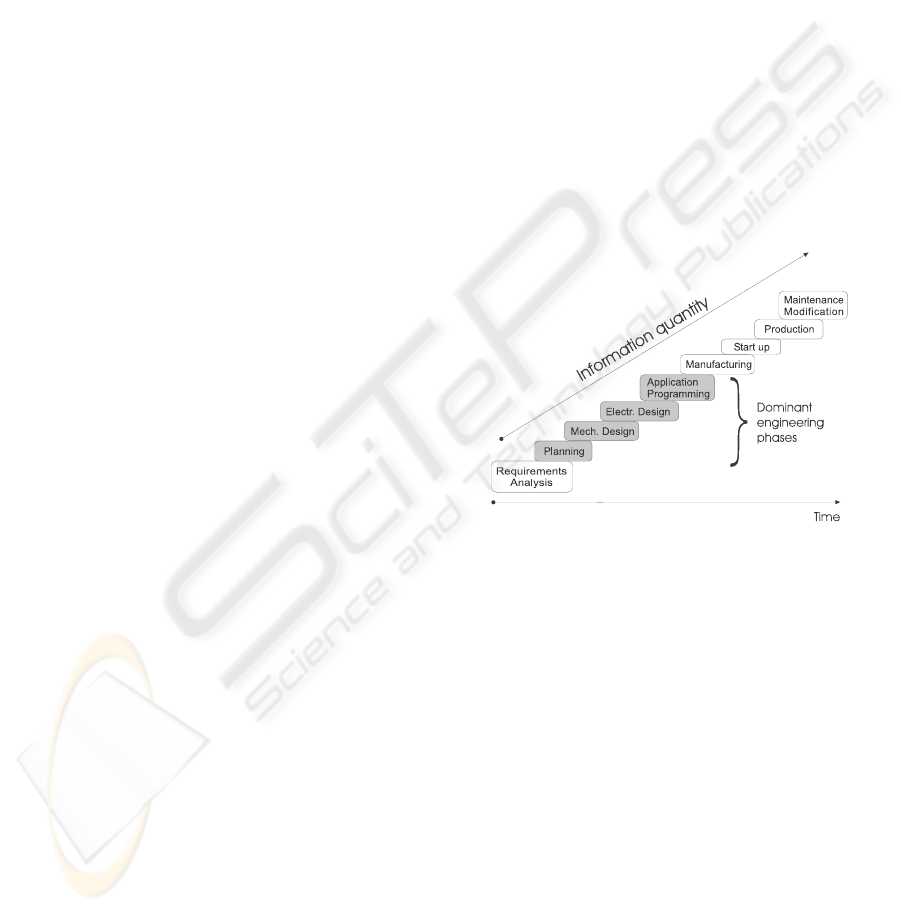
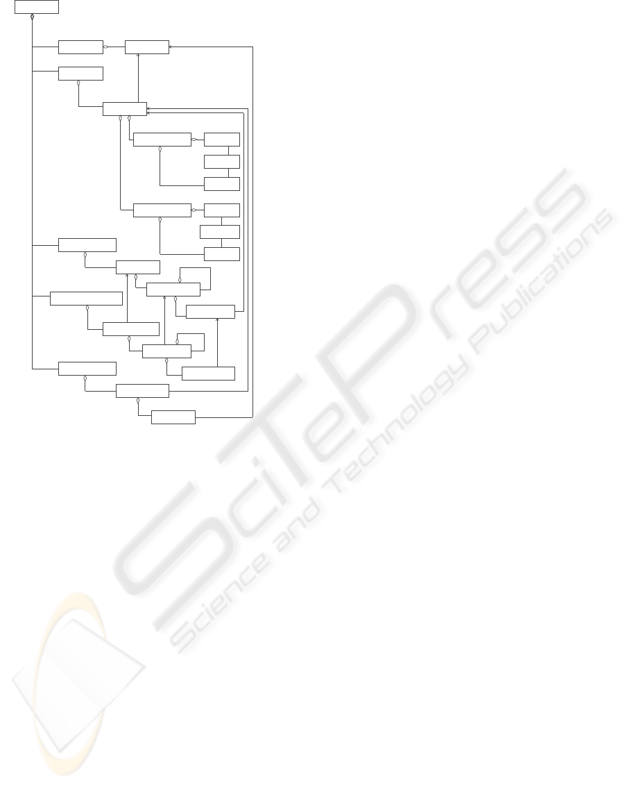
The development of these three subsystems is the
main task within the whole engineering of the mecha-
tronic system. Normally, the life cycle of a mecha-
tronic system is subdivided into the following phases:
requirements analysis, planning, mechanical design,
electric/electronic design, application programming,
manufacturing, start up, production, maintenance and
modification as illustrated in figure 1.
Each subsystem is developed within the corre-
sponding engineering phase. Additionally, each of
these phases can contain simulations to verify the
phase solution.
Figure 1: Phase definition in special purpose machine engi-
neering
In the past, the development of mechatronic sys-
tems has often been dominated by mechanical de-
sign. The design of software/electronic components
was added later. This has led to a poor development
approach (Isermann, 1996; Gausemeier et al., 2001).
Today the work flow is recursive and solutions from
earlier phases have to be taken into consideration per-
manently.
Software tools which are used in the phases of
planning, mechanical design, electric/electronic de-
sign and application programming deal with most of
the tasks in the entire engineering. They determine
also most of the engineering data. Other phases use
the engineering data from these four phases and make
rarely changes or replenishments. For this reason, the
discussion in the remaining sections will focus on the
engineering data models in these four phases.
GENERAL ENGINEERING DATA MODEL IN SPECIAL PURPOSE MACHINE ENGINEERING
349
2 AVAILABLE DATA MODELS
AND SOFTWARE TOOLS IN
SPECIAL PURPOSE MACHINE
ENGINEERING
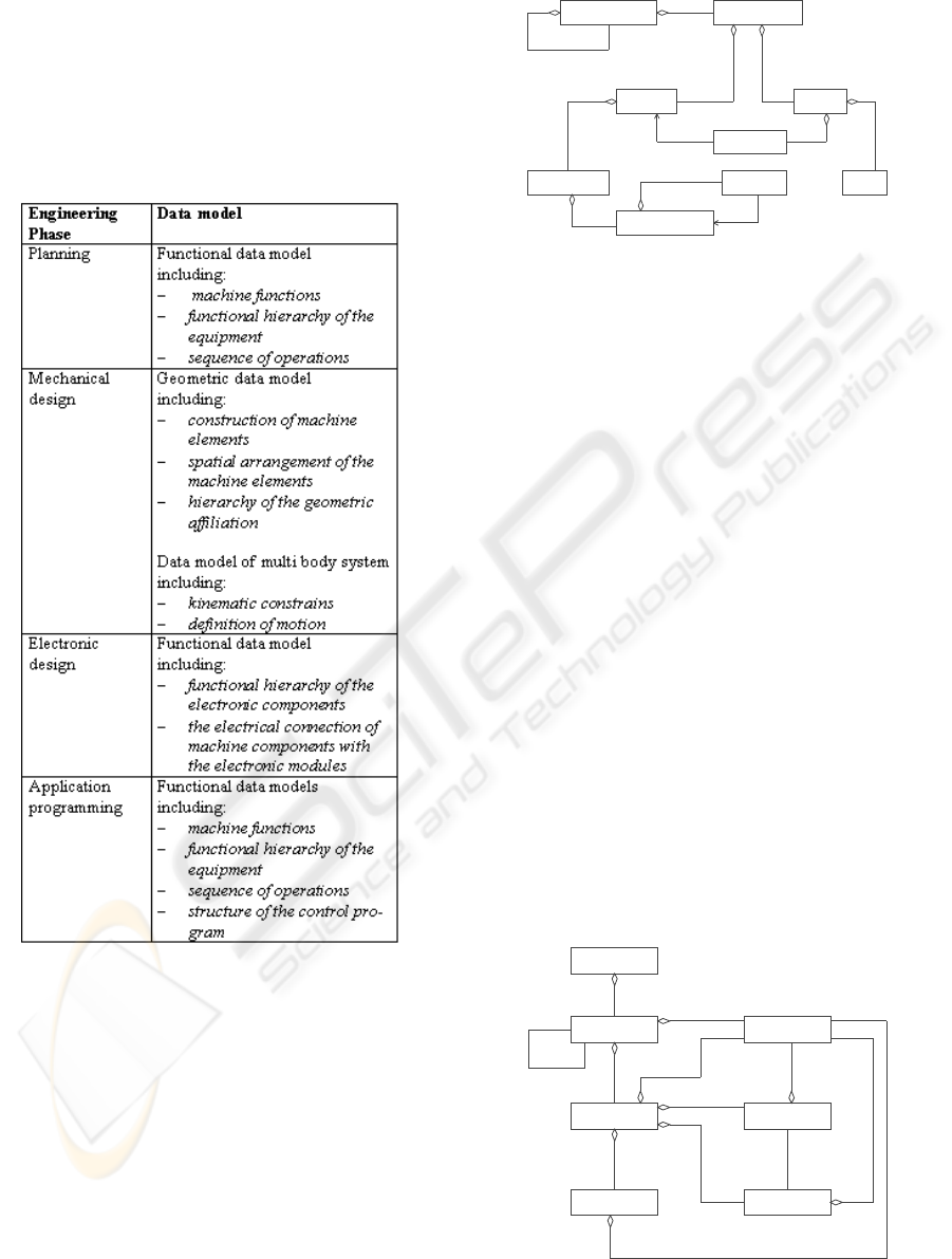
The data models and corresponding engineering
phases are listed in figure 2.
Figure 2: Data models in special purpose machine engineer-
ing
2.1 Data models in planning phase
As illustrated in figure 3 using UML notation, the data
model in the planning phase is the functional model
derived from the function analysis. This data model
describes the hierarchically on one hand the functions
this machine provides, and on the other hand the se-
quence of operations in this machine.
A mechatronic system (see figure 3) is abstracted
and analyzed in this phase as a group of Functio-
nUnits which interact with each other. Each Func-
FunctionGroup
ActionInstance
FunctionUnit
Actuator
Connection
Relation
Input
Output
Signal
1
0..*
1
0..*
1
0..*
1
1
1
1 0..*
1
0..*
1
1
1
0..*
1
0..*
Figure 3: Functional data model in planning phase
tionUnit executes the predefined action when the
Input conditions are given. The execution result
serves as Input information for other FunctionUnits.
The FunctionUnits connect through their Inputs and
Outputs with each other. This map of Connections
defines the functional interactions within the system.
The order of ActionInstances describes the sequence
of machine operation.
One software tool used in this phase is eM-Planner
of Tecnomatix (Tecnomatix, 2005). This engineering
tool provides the ability to model and plan manufac-
turing processes for entire plants, lines and single op-
erations.
The functional analysis and functional data model
of this phase is the basis of mechanical, elec-
tric/electronic design and control application pro-
gramming. It can be changed according to the re-
quirements of coming phases.
2.2 Data models in mechanical
design
Data models in this phase are categorized into two
different ways:
Environment
Object
Hull
Section
Grippoint
Gripper
Frame
1
1
1
1
1
1
1 0..*
1
0..*
1 1
1
1..*
1
1..*
1
1
1
1..*
0..*
0..*
1
0..*
Figure 4: Geometric data model
ICINCO 2005 - SIGNAL PROCESSING, SYSTEMS MODELING AND CONTROL
350
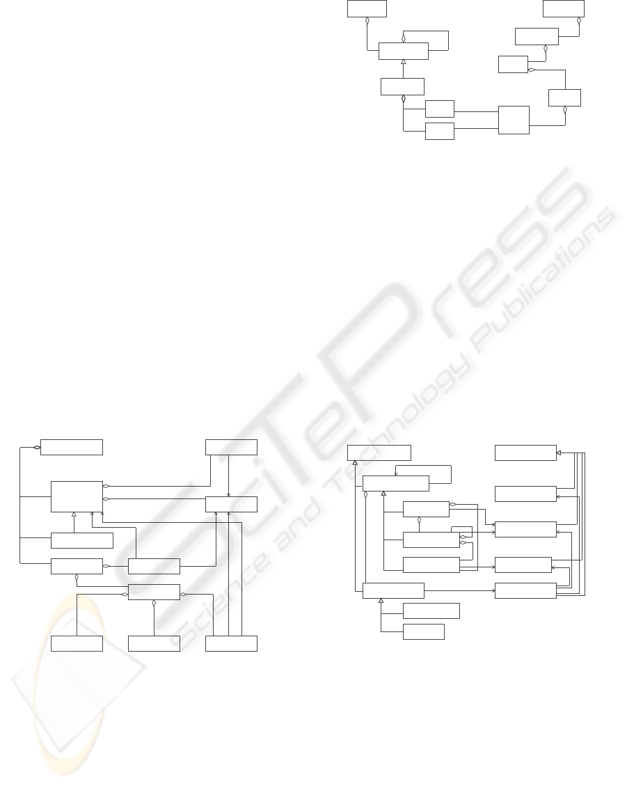
• geometric structure: the geometric data models
are used in CAD software tools. They describe
the mechanical structure of a mechatronic system.
Figure 4 illustrates a geometrically oriented data
model (Uthoff, 1998; Rossmann, 1993). Multiple
Objects could be involved in one Environment.
One Object is separated in several Sections and
substructured into several Hulls. Each Hull rep-
resents a basic geometric body. All of them have
a Frame which describes their spatial position and
orientation. The connection between Gripper and
Grippoint defines the geometric binding of bodies.
• Multi body system: in these data models a mecha-
tronic system is regarded as a multi body system
(MBS) as illustrated in figure 5 (Otter, 1995; Reif,
1998; Sch
¨
afer and L
´
opez, 1999). Each subsystem
in an MBS has three basic components: Force,
Body and Joint. Force describes the general in-
put and output of the subsystem, as well as Body is
the geometric description. Joint defines the kine-
matic constrains and describes the interaction be-
tween the subsystems. This data model is used ba-
sically in the mechatronic simulation to analyze the
kinematic and kinetic characteristic. The definition
of the machine function, that has been carried out
in the planing phase, determines the kinematic mo-
tion.
MBS
InertialSystem
Interact
Joint
Part
Body
Sensor
Frame
Force
Member
Connect
1
1
0..*
1
0..*
0..1
2
1
0..*
2
0..*
2
0..*
Figure 5: Data model of multi body system
2.3 Data models in electric design
Electric design in special purpose machine engineer-
ing is different from electric design in modul develop-
ment. The configuration of BUSSystems, the assign-
ment of system components (FunctionUnits) to the
BUSSystem and the design of the electrical cabling
between system components and BUSMember are in
the focus.
FunctionGroup
BUSMember
FunctionUnit
BUSSystem
Equipment
IOChanal
IOPin
IOModul
Input
Output
1..*
0..1
1
1..*
8, 16
1..*
0..1
1
0..*
0..*
1..*
0..*
Figure 6: Data model in electric design
Figure 6 illustrates a part of the model that de-
scribes the data processed in electric design.
On the left hand side the functional equipment hi-
erarchy is shown as defined in planning phase. On
the right hand side is the hierarchy of Bus-system.
The Association between Input/Output and IOPin
describes the electrical cabling.
2.4 Data models in control
application programming
FunctionObject
EquipmentObject
ElecResource ControlModulER
ControlModulFG
ControlObject
ControlProgram
SensorActor
FunctionGroup
FunctionUnit ControlModulFU
Machine
UserIO
0..*
0..*
0..*
0..*
0..*0..*
0..*
0..*
0..*
Figure 7: Data model in control application programming
Figure 7 gives a data model in control application
programming (Brandl, 1999; Lutz, 1999). This data
model is separated into two hierarchies. On the left
side is the functional equipment hierarchy as defined
in planning phase, and on the right side the hierar-
chy of the control program. Each FunctionGroup
and FunctionUnit in the functional hierarchy has a
related ControlObject in the hierarchy of the control
program. The data planned in functional analysis, e.g.
sensors/actuators and input/output are also needed for
the control programs and the control modules.
GENERAL ENGINEERING DATA MODEL IN SPECIAL PURPOSE MACHINE ENGINEERING
351
2.5 Evaluation of the data models
As discussed in the sections before, each data model
is used specifically in one engineering phase and
processes the phase-specific data. These data models
contain not only phase-specific data but also common
data. For example, the definition of input and output
in the functional analysis in the planning phase is used
in mechatronic simulation and control programming.
However the common data are not shared between the
models of the different engineering phases or the dif-
ferent engineering tools respectively. The data can not
be reused. The new requirements 1, 2 and 3 from en-
gineering as listed in the part 1.1 are not satisfied in
these data models.
3 CONCEPT OF THE GENERAL
ENGINEERING DATA MODEL
The idea of the General Engineering Data Model
(GED) is that all software tools in all engineering
phases use only one single data model. All of them
share the same data from this general data model.
These software tools access this single data model and
retrieve the necessary data from it and store the phase
result back into this data model.
For example, the software tool in the planning
phase creates and stores the functional hierarchy of
a mechatronic system in the GED. The software tool
in mechanical design can accept this functional hi-
erarchy and build the model for multi body system.
This means that the functional model from planning
phase is reused for modelling in the kinematic simu-
lation. The software tool in control application pro-
gramming can use this functional hierarchy directly
to facilitate the design of control program. The later
phases can change and update the data coming from
earlier phases straightforward.
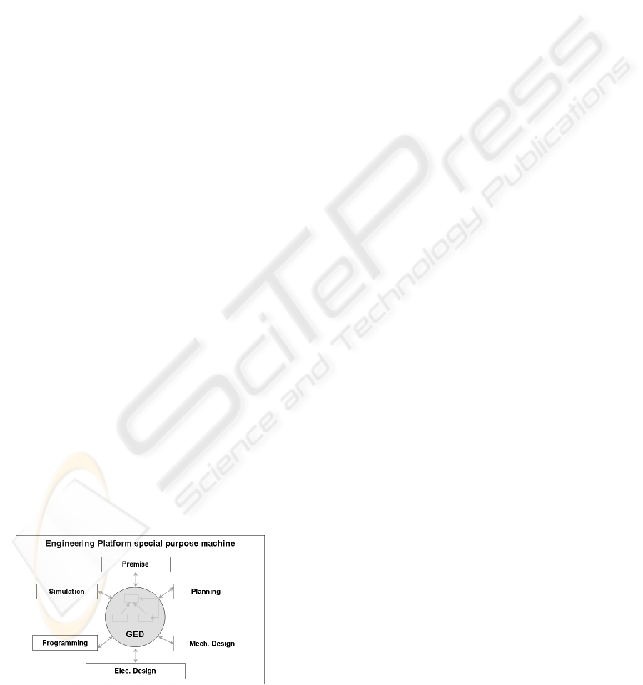
Figure 8 illustrates the position of the General En-
gineering Data Model in special purpose machine en-
gineering. In this case, the software tools do not have
Figure 8: Position of GED in special purpose machine en-
gineering
proprietary data bases. They use the GED to share
data. The data exchange between the software tools is
executed through the GED.
3.1 Structure of the General
Engineering Data Model
Figure 9 shows the basic data structure of the GED
using UML notation. The main data of engineering
are abstracted and separately modelled in SystemU-
nit. It contains the shared data of multiple engineer-
ing phases. The mechanical binding is modelled in
DynamicInterface, and the electrical binding is sep-
arately modelled in ControlInterface. SystemUnit
and its sub-hierarchy build the backbone of the GED.
The geometric data are separated from SystemUnit
because they can be modelled and assigned otherwise.
For example, the body of a cylinder could be assigned
with its piston together as a component. In this case it
will be used and referenced from the kinematic simu-
lation. Just the same cylinder body could be also as-
signed with its fixing plate together as a group. Multi-
body-systems-analysis takes advantage of this assign-
ment to analyse the kinetic characteristic.
The structure of FunctionHierarchy is the same
as illustrated in figure 3 in planning phase. The struc-
ture of ControlModuleHierarchy and its assignment
to a FunctionHierarchy are also the same as fig-
ure 7. The engineering data in FunctionUnit are ab-
stracted in SystemUnit and ControlInterface. Each
FunctionUnit has a reference on an appropriate Sys-
temUnit. A program module accesses the definition
of input/output and sensor/actuator indirectly through
FunctionUnit to SystemUnit in this case.
The modelling of the dynamic characteristic is
wrapped in MKSHierarchy.
3.2 Evaluation of the General
Engineering Data Model
The General Engineering Data Model connects the
software tools used in the engineering of special pur-
pose machines.
The advantage of this new approach is a smaller
number of interfaces. Each tools needs only a sin-
gle interface to the GED. The earlier implementation
of proprietary interfaces for the direct data exchange
between the software tools is not neccesary anymore.
The number of interfaces for the data exchange re-
duces from n(n-1) to n, in which n is the number of
software tools.
Another advantage is a better quality of the engi-
neering data. The GED allows all software tools to
store and access their engineering data. The change
of data in one software tool directly updates the data
ICINCO 2005 - SIGNAL PROCESSING, SYSTEMS MODELING AND CONTROL
352
ControlModuleHierarchy
MKSHierarchy
FunctionHierarchy
DynamicInterface
ControlInterface
ControlProgram
Subsystem
FunctionGroup
UnitModule
GroupModule
FunctionUnit
Geometric
SystemUnits
SystemUnit
Cell
Body
Part
GED
Interaction
CInput
Connection
MOutput
COutput
MInput
Figure 9: Compositions/Aggregations in the General Engi-
neering Data Model (not shown are e.g. class hierarchy)
status of the other software tools. The data is consis-
tent and up-to-date.
According to the requirements in 1.1,
1. The data in the GED is available across all en-
gineering phases, from planning, mechanical and
electrical design, control application programming
and so on.
2. The GED separates the engineering data from the
phase-specific hierarchy and allows the software
tools to share the phase-independent engineering
data.
3. The data in the GED is redundance-free. This im-
proves the data change management.
4. The GED can be extended. It allows to integrate
data of new software tools because the data are cou-
pled through references.
A prototypical implementation of the GED has
been used for the engineering of an assembly cell at
Bosch. The GED has been used to cauple software
tools for cell-planning and for cell-programming.
Due to the GED the first of the five steps (modeling,
configuration, module test, program completion and
integration test) in the programming of the cell is gen-
erated automatically. It shortes the development time
by more than 20%, and therefore, the engineering cost
is reduced.
Moreover, the data has always been kept up-to-date
and coordination effort within the engineering team
has been significantly reduced. The improvement has
been estimated to a 20% reduction in development
time and a 25% better data quality.
4 CONCLUSION
The development of special purpose machines is a
continuous and recursive process. It is divided into
several engineering phases. The software tools and
their data models currently used in each phase are in-
dependent from each other. It is difficult to exchange
the data between these phases and to keep the data
consistent. Engineering needs a new concept to im-
prove the cooperation of these software tools.
The GED summarizes the data processed in each
engineering phase and builds a data base for all en-
gineering phases. It connects the software tools and
makes the engineering process smooth. Through the
separation of engineering data from its phase-specific
system hierarchy, all of the phase-neutral data is cen-
trally managed. The GED retains the phase-specific
system hierarchies, which refer to engineering data.
This avoids the data redundance and improves the
data availability across the entire engineering process.
REFERENCES
Brandl, T. (1999). Anlageninformationssystem - Informa-
tionsmodell und Erstellungsystematik. Jost Jetter Ver-
lag, Heimsheim.
Ciocoiu, M., Nau, D. S., and Gruninger, M. (2001). On-
tologies for integrating engineering applications. In
Transaction of the ASME, Journal of Computing and
Information Science in Engineering, volume 1, pages
12–22.
EPLAN (2005). Reibungsloser Informationsfluss zwischen
allen Abteilungen bringt Ihr Engineering auf Erfol-
gsspur. Technical report, EPLAN Software and Ser-
vice.
Gausemeier, J., Flath, M., and Mohringer, S. (2001). Con-
ceptual design of mechatronic systems supported by
semi-formal specification. In Proceedings of the
IEEE/ASME international Conference on Advanced
Intelligent Mechatronics, pages 888–892, Como,
Italy.
Germer, C., Hansen, U., Franke, H.-J., and B
¨
uttgenbach,
S. (2001). Produkentwicklung mit neuen technolo-
gien - mechatronik vs. mikrosystemtechnik. In 4.
GENERAL ENGINEERING DATA MODEL IN SPECIAL PURPOSE MACHINE ENGINEERING
353

VDI Mechatronik Tagung 2001 Innovative Produkten-
twicklungem, pages 19–36.
Isermann, R. (1996). Modeling and design methology
for mechatronic systems. In IEEE/ASME Trans. on
Mechatronics, volume 1 of 1, pages 16–28.
Isermann, R. (1999). Mechatronsche Systeme. Springer-
Verlag Berlin.
Keil, A. and Schmidt, M. (2001). Modellierung
und simulation elektromechanischer systeme durch
werkzeugkopplung. In 4. VDI Mechatronik Tagung
2001 Innovative Produktentwicklungem, pages 112–
126.
K
¨
ubler, R. (2000). Modulare Modellierung und Simulation
mechatronischer Systeme. VDI-Verlag D
¨
usseldorf.
Lutz, R. (1999). Softwaretechnik f
¨
ur maschinennahe
Steuerungsfunktionen bei Fertigungseinrichtungen.
Jost Jetter Verlag, Heimsheim.
Otter, M. (1995). Objektorientierte Modellierung mechatro-
nischer Systeme am Beispiel geregelter Roboter. VDI-
Verlag, D
¨
usseldorf.
Pelz, G. (2001). Modellierung und Simulation mechatron-
ischer Systems. H
¨
uthig Verlag Heidelberg.
Reif, T. (1998). Zur objektorientierten Modellierung aktiver
Mehrk
¨
orpersysteme. VDI-Verlag D
¨
usseldorf.
Rembold, U., Nnaji, B. O., and Storr, A. (1994). CIM: Com-
puteranwendung in der Produktion. Addison-Wesley.
Rossmann, J. (1993). Echtzeitf
¨
ahige, kollisionsvermeidende
Bahnplanung f
¨
ur Mehrrobotersysteme. Universit
¨
at
Dortmund.
Sch
¨
afer, C. and L
´
opez, O. (1999). An Object-oriented robot
model and its integration into flexible manufacturing
system. In I. Imam, Editor, Mulitple Approaches to
Inteligent Systems. Springer.
Starke, G. (2001). Virtual reality und simulation als integri-
erte werkzeuge f
¨
ur die entwicklung mechatronischer
systeme. In 4. VDI Mechatronik Tagung 2001 Innov-
ative Produktentwicklungem, pages 1–17.
Tecnomatix (2005). eM-Planner: Planning, Analyzing and
Managing Manufacturing Process. Technical report,
http://www.tecnomatix.de/.
Uthoff, J. (1998). Offenes, modulares System zur zellenori-
entierten Robotersimulation. VDI-Verlag D
¨
usseldorf.
VDI (2003). Digitale Planung bringt Sicherheit. Technical
report, VDI.
Welp, E. G., Lippold, C., and Bludau, C. (2001). Ein system
zur objektorientierten modellierung mechatronischer
produktkonzepte (modcode). In 4. VDI Mechatronik
Tagung 2001 Innovative Produktentwicklungen, pages
93–112.
Westk
¨
amper, E. (2002). Die digitale fabrik - interview
mit engelbert westk
¨
amper: Intelligente maschinen
m
¨
ussen kommunizieren und sich selbst organisieren.
Technical report, Siemens: Pictures of the Future.
ICINCO 2005 - SIGNAL PROCESSING, SYSTEMS MODELING AND CONTROL
354
