
HIGHLY ACCURATE INTEGRATION OF TRACK MOTIONS
Michael Kleinkes, Angela Lilienthal, Werner Neddermeyer
University of Applied Science in Gelsenkirchen
Neidenburger Str. 43, 45897 Gelsenkirchen
Keywords:
Industrial Robots, 7
th
axis, linear track, offline programming.
Abstract:
According to the largeness of the workpieces in several industrial environments, a great number of industrial
robots is placed on external track motions, so called 7
th
axes, as for automotive or aircraft industries. Flexible
automation today requires absolute high accuracy. For example modern robotics deals with offline program-
ming, copying programs between similar working cells, reflecting programs or image processing for 3D-pose
estimation. All these tasks need absolute high accuracy and in fact, there have been many investigations for
increasing the accuracy of single robots in the past few years.
In contrast to that the use of track motions will dramatically increase the position error and badly influence
the static behaviour of the robot system. The main reasons for these additional errors are the incorrect identi-
fication of the main track direction and furthermore, very crucial, the non-linearities of the TCP (Tool Center
Point) during the robots motion on the track. This article will introduce a new method of identification and
mathematical integration of linear tracks. At first we present the method for measuring and generating profiles
of single tracks by making use of the discrete fourier transformation (DFT) and cubic spline interpolation.
Then a method for recalculating offline generated programs for real environments is presented, followed by a
method for copying programs taking two profiles of track motions into consideration. Finally some measure-
ment results are shown.
1 INTRODUCTION
Increasing demands on the flexible automation, e.g.
offline programming of robot motions or the applica-
tion of more and more complex tasks like sealing of
carbodies, require robot systems with absolute high
accuracies. In the past there was done a lot of re-
search work and investigations to increase the accu-
racy of robots by an individual identification (Denavit
and Hartenberg, 1955), (Maas, 1997) of internal para-
meters, so that robots with a high accuracy option are
available (Nitschke, 2002). From the experience the
inaccuracy of these robots is almost less than 1 mm.
In many cases of the automotive industry, the ro-
bot’s workspace is extended by external track motions
which deteriorates the accuracy of the system in a
significant manner about several millimetres or more.
This alarming fact is not compatible to the demands
on the flexible automation at all and additionally is ne-
glected by scientists and robot manufactorers as well.
Offline programming, copying or reflecting pro-
grams or 3D pose estimation requires a coordination
of the track and the robot motion, that means an inte-
gration into the robots coordinate system. The meth-
ods of measurement, identification and mathematical
integration of track motions are shown exemplary for
an ABB robot. Similar computations for other types
of robots, e.g. KUKA or FANUC, are possible as
well. Figure 1 will give you an overview of the im-
portant robot coordinate systems.
The alignment frame, as shown in figure 1, pro-
vides the connection of the track motion to the robot.
The ABB controller is computing the main track di-
rection from a frame containing quaternions (Convay
and Smith, 2003), which indicates the rotation from
the robot’s world frame to the track. It is obvious,
that the similar parameters for the track integration
have to be worked out for each type of robot, e.g.
KUKA, COMAU or FANUC. It is an essential knowl-
edge, that any type of controller unit is modelling
tracks as straight lines, where the incorrect identifi-
cation of the main track direction and - very crucial
- the non-linearities of the robot’s TCP during a mo-
tion on the track, the so called robot’s twist, are not
11
Kleinkes M., Lilienthal A. and Neddermeyer W. (2005).
HIGHLY ACCURATE INTEGRATION OF TRACK MOTIONS.
In Proceedings of the Second International Conference on Informatics in Control, Automation and Robotics - Robotics and Automation, pages 11-15
DOI: 10.5220/0001169100110015
Copyright
c
SciTePress
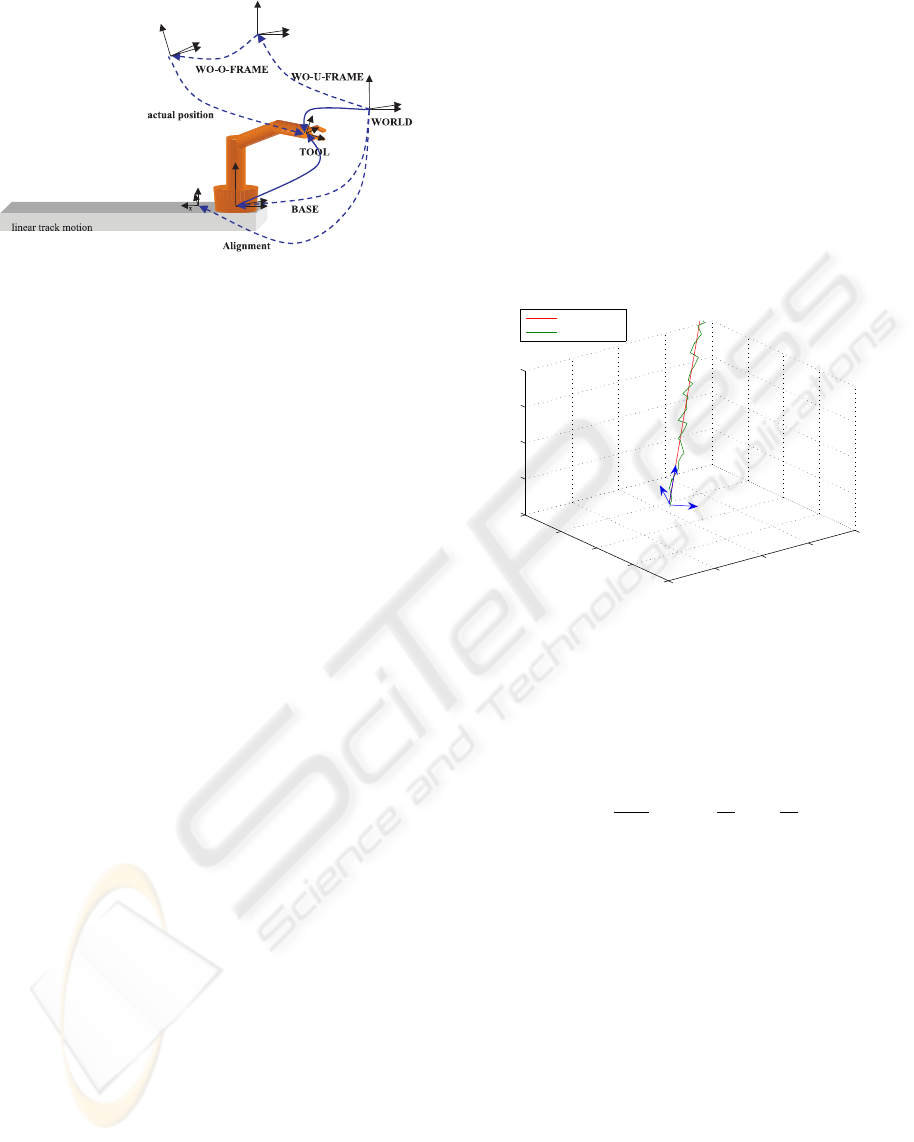
Figure 1: Coordinate systems
taken into consideration. The offline generated robot
motions, the actual positions, are related to the work-
piece, which is provided by the so called workobject
(WO-U- and -O-FRAME) of the robot controller in-
terface.
2 IDENTIFICATION OF TRACK
MOTIONS
For the identification of track motions we make use
of a mobile coordinate measurement device, e.g. a
laser tracker. Due to the computation of the robot’s
behaviour under motion on the track, it is aimed to
identify the robot’s coordinate system at n positions.
For that, first the optimal number of positions is to be
found by the spectral analysis (Press et al., 1989) of a
fine scanned motion.
2.1 Fine scanning
For the evaluation of the optimal number of posi-
tions where a frame identification is necessary, a sin-
gle high resolution scan of the robots TCP during a
motion on a straight line with constant joint config-
uration, that means movement only by the track, is
generated. The movement is carried out with low and
constant velocity V and the scan mode is switched on
high resolution and discrete in time (sampling inter-
val: dt).
Assuming that one axis of the measurement frame
points in the direction of the expected line, the sum
of the 3D coordinates x
k
, y
k
and z
k
contains the
command function - a ramp function s
k
- plus the
non linear twist motion, which is of interest. After
the elimination of the ramp function, the Fourier
transform of the h
k
’s contains the spectrum of the
non-linearities of the track:
From
s
k
= k · ∆, k = 0, 1, ..., N − 1 (1)
and
∆ = V · dt (2)
follows
h
k
= x
k
+ y
k
+ z
k
− s
k
(3)
where the x
k
, y
k
and z
k
are the 3D scan of the TCP
(see figure 2).
0
10
20
30
40
0
10
20
30
40
0
10
20
30
40
x
y
z
command line
error motion
measurement frame
Figure 2: command and error motion
The DFT becomes
H(f
n
) = X(f
n
) + Y (f
n
) + Z(f
n
) − S(f
n
) (4)
from
f
n
=
n
N∆
; n = −
N
2
, ....,
N
2
(5)
follows that
H(f
n
) =
Z
∞
−∞
h(s)e
−j2πf
n
s
ds
≈
N−1
X
k=0
h
k
e
−j2πf
n
s
k
∆
= ∆
N−1
X
k=0
h
k
e
−j2πkn/N
(6)
From eq.5 it is obvious that the frequency is of the
unit mm
−1
.
Figure 3 gives an example about a spectrum taken
from a typical arrangement.
If a detection of errors greater than 0.5 mm is re-
quired, it is obvious by the sampling theorem that it is
essential to identify the robot coordinate frame each
100 mm (= 1/(2 · 0.005mm
−1
)).
ICINCO 2005 - ROBOTICS AND AUTOMATION
12
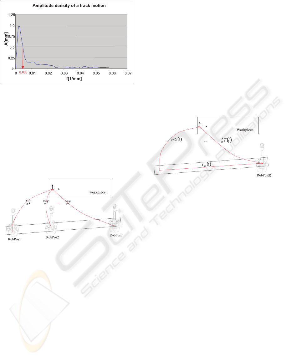
Figure 3: Example of a track spectrum
2.2 Generation of track profiles
Once the sampling rate is known, it is possible to gen-
erate the continuous of the non-linear robot behaviour.
At first the robot’s coordinate frame is identified at n
positions on the track. The measurements are done
using the same set up points at each position. That
means the robot is taken as a rigid body, because of
it’s high repeatability.
Figure 4: Measurement of the axis profile
Figure 4 shows the relations if the workpiece, to
which the offline generated programs are related to, is
already identified. The results are n transformations
where the six dimensions of freedom are implicitly
dependent on the value of the track:
Ri
W
T = f
i
(α(l
i
), β(l
i
), γ(l
i
), t
x
(l
i
), t
y
(l
i
), t
z
(l
i
))
(7)
For the computation of a continuous description, we
make use of the cubic spline interpolation procedure
(Dautray, 2000), which connects the discrete pairs of
varieties (α
i
, l
i
), (β
i
, l
i
), etc. to smooth and also
smooth in the first derivative functions, so that the
continuous form becomes:
R
W
T (l) = f (α(l), β(l), γ(l), t
x
(l), t
y
(l), t
z
(l)) (8)
Note, that these are the relations where the track is
not coordinated to the robot motion. For a connection
to the robot base, the axis transformation, which is
dependent on the value l of the robot’s position on the
track as well, is computed by:
T
ax
(l) =
I l ·
~
Ax
Dir
0
T
1
(9)
where I is the 3 × 3 identity matrix and
~
Ax
Dir
is
the controller owned normalised axis direction (which
has to be worked out individually belonging to the
type of robot). From eq.8 and 9 the workobject frame
W O(l) becomes:
W O(l) = T
ax
(l) ·
R
W
T (l) (10)
which is shown in figure 5.
Figure 5: Connection to track motion
3 MODIFICATION OF ROBOT
PROGRAMS
The modification of robot programs has to be divided
into two parts. The first case is copying offline gen-
erated motions to a real profile, whereas the second
is copying programs between similar working cells
taking both - the master and the slave - profile into
consideration.
3.1 Modulation of offline generated
robot programs
In figure 6 you can see the robot’s behaviour under
a motion on it’s 7
th
axis. Note that the predefined
controller owned workobject is WO1 which is valid
for the robot position RobPos1 without moving on the
track. But under robot motion and it’s twist it points
from the position RobPos n to the dashed workpiece
which of course is not there.
From the splined workobject and the actual value
on the track we know all relations, so as a conse-
quence the corrected workframe becomes:
T
corr
= (W O1)
−1
· W O(l) · T
offline
(11)
HIGHLY ACCURATE INTEGRATION OF TRACK MOTIONS
13
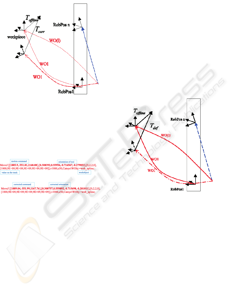
Figure 6: Workobjects and twist
The example shown in figure 7 illustrates the modifi-
cations to the motion commands in the robot language
RAPID, which is characteristic for ABB robots.
Figure 7: Modification of robot commands
The motion commands are always related to the
coordinate system of the workpiece and the orienta-
tion of the tool is - a speciality of ABB robots - ex-
pressed in quaternion notation. The value on the track
has to be given explicitly for each robot motion, be-
cause of the overdetermination of the inverse problem
when using a 7
th
axis - that means for sure an ad-
ditional degree of freedom. The choice of the prede-
fined workobject is individually possible for any com-
mand.
So- what the proposed procedure does is just to re-
place the motion commands - translation and orien-
tation - with the corrected ones. That means that the
corresponding software tools won’t change the struc-
ture of the robot file. It will be a kind of artificial post
teaching of robot programs.
3.2 Copying programs between
similar robot systems
From chapter 3.1 we are able to modify offline gen-
erated robot files with the behaviour of the real robot
and due to that, create accuracies for the robot sys-
tems, which are rather identical to those of single ro-
bots.
But what is to be done if two track motions are
of interest in the case of copying programs from one
station to another? The solution is the computation
of so called quasi offline programs under considera-
tion of the track from which the programs should be
copied. That means: compute the inverse of the de-
scribed method as illustrated in figure 8.
Figure 8: Copy programs
Now the defined or teached workframes T
def
of the
robot master are known which have to be recalculated
into an ideal perpendicular offline world (T
offline
):
T
offline
= (W O(l))
−1
· W O1 · T
def
(12)
These quasi offline generated programs from the ro-
bot master profile can be taken as the input files for
the method described in chapter 3.1 to create the con-
verted motions for the slave system.
4 RESULTS
Figure 9 illustrates the results of a test program con-
taining 12 work frames. The blue columns show the
errors of the conventional robot system whereas the
red ones show the errors of the modified workframes.
ICINCO 2005 - ROBOTICS AND AUTOMATION
14
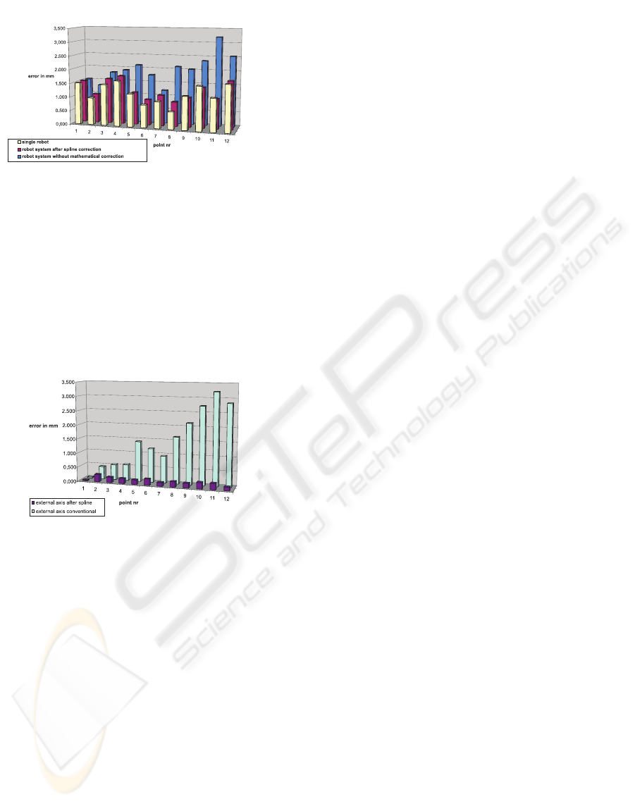
Figure 9: Results 1
For a validation the yellow ones show the errors of the
robot itself.
So the final improvement is demonstrated by figure
10. The errors caused only by the track are shown
by the bright blue columns for the conventional sys-
tem and - the dark blue ones - for the modified robot
motions.
Figure 10: Results 2
5 CONCLUSION
As a conclusion we want to emphasise the compensa-
tion of errors caused by external track motions. That
means the
• accuracy of the robot system is nearly identical to
that of the single robot.
• the worst case for the inaccuracy of copied pro-
grams is the doubled inaccuracy of one single ro-
bot.
A future prospect will be the implementation into
the robot control, that means including the measured
splines directly into the position control of the robot
as an option for high accurate robots. A further step
will be the implementation into continuous path mo-
tions.
REFERENCES
Convay, J. and Smith, D. (2003). On quaternions and octo-
nions. A K Peters, Massachusetts.
Dautray, R. (2000). Mathematical analysis and numerical
methods for science and technology. Springer, Lon-
don.
Denavit, J. and Hartenberg, R. (1955). A kinematic nota-
tion for lower-pair mechanism based on matrices. In
ASME Journal of Applied Mechanics 22, pages 215–
221.
Maas, H. G. (27.7.-1.8.1997). Dynamic photogrammetric
calibration of industrial robots, spie’s 42 annual meet-
ing, san diego. In Videometrics V, SPIE proceedings
Series Vol. 3174.
Nitschke, H. (2002). Zur Bestimmung geometrischer Pa-
rameter von Industrierobotern. Bayrische Akademie
der Wissenschaften, Dissertation, TU Munich.
Press, W. H., Teukolsky, S. A., Vetterling, W. T., and Flan-
nery, B. F. (1989). Numerical Recipes in C. Cam-
bridge University Press.
HIGHLY ACCURATE INTEGRATION OF TRACK MOTIONS
15
