
ADAPTIVE VISUAL-FORCE CONTROL IN UNKNOWN
WORKSPACES
Jorge Pomares, Fernando Torres, Laura Payá
Physics, Systems Engineering and Signal Theory Department
University of Alicante, Alicante, Spain
Keywords: force control, image-based control, autocalibration.
Abstract: This paper proposes the definition of a new adaptive system that combines visual and force information. At
each moment, the proportion of information used from each sensor is variable depending on the adequacy of
each sensor to control the task. The sensorial information obtained is processed to allow the use of both
sensors for controlling the robot and avoiding situations in which the control actions are contradictory.
Although the visual servoing systems have certain robustness with respect to calibration errors, when the
image-based control systems are combined with force control we must accurately know the intrinsic
parameters. For this purpose an adaptive approach is proposed which updates the intrinsic parameters during
the task.
1 INTRODUCTION
Image-based visual servoing is now a well-known
approach for positioning the robot with respect to an
object observed by a camera mounted at the robot
end-effector (Hutchinson et al. 1996). However, in
applications in which the robot must interact with
the workspace, the visual information must be
combined with the sensorial information obtained
from the force sensor. A great number of approaches
employed for fusing the information obtained from
both sensors have been based, up to now, on hybrid
control. Concerning hybrid visual-force systems, we
should mention studies like (Baeten and De
Schutter, 2002) which extend the “task frame”
formalism (Bruyninckx and De Schutter, 1996). In
(Namiki et al., 1999) a system for grasping objects
in real time, which employs information from an
external camera and that obtained from the force
sensors of a robotic hand, is described. Another
strategy used for the combination of both sensorial
systems is the use of impedance control. Based on
the basic scheme of impedance control, we should
mention several modifications like the one described
in (Morel et al., 1998), which adds an external
control loop that consists of a visual controller
which generates the references for an impedance
control system. In works such as (Tsuji et al. 1997),
the use of virtual forces applied to approaching tasks
without contact, is proposed.
In this paper we are not interested in image
processing issues, so that the tracked target is
composed of four grey marks which will be the
extracted features during the tracking. This paper
proposes the definition of a new adaptive system
which combines visual and force information.
Similar approaches has been developed in works
such as (Baeten et al., 2002; Olson et al. 2002)
however these approaches do not consider the
possibility of both sensors providing contradictory
information at a given moment of the task. Thus, in
unstructured environments it can happen that the
visual servoing system establishes a movement
direction that is impossible according to the
interaction information obtained from the force
sensor. In this paper, we consider this possibility and
the sensory information obtained is processed to
allow the use of both sensors for controlling the
robot.
An original aspect of the proposed system is that
the proportion of information used from each sensor
is variable and depends on the criterion described in
Section 4. At each moment, this criterion provides
information about the sensor more adequate to
develop the task.
196
Pomares J., Torres F. and Payá L. (2005).
ADAPTIVE VISUAL-FORCE CONTROL IN UNKNOWN WORKSPACES.
In Proceedings of the Second International Conference on Informatics in Control, Automation and Robotics - Robotics and Automation, pages 196-201
DOI: 10.5220/0001169001960201
Copyright
c
SciTePress

This paper is organized as follows: The main
characteristics of the trajectory to be tracked and the
notation used is described in Section 2. Section 3
shows the way in which the tracking of the trajectory
in the image is carried out. In Section 4, the strategy
used for fusing force information with that from the
visual servoing system is described. Section 5
describes how the fusion system manages situations
in which contradictory control actions are obtained
from both sensorial systems. The autocalibration
system employed to update the intrinsic parameters
is described in Section 6. In Section 7, experimental
results, using an eye-in-hand camera, confirm the
validity of the proposed algorithms. The final
section presents the main conclusions arrived at.
2 NOTATION
In this paper, the presence of a planner, which
provides the robot with the 3-D trajectory, γ(t), to be
tracked (i.e., the desired 3-D trajectory of the camera
at the end-effector), is assumed. These trajectories
are generated from a 3-D geometric model of the
workspace, so that it is necessary to employ a visual
servoing system that performs the tracking of the 3-
D trajectory using visual information and, at the
same time, tests whether it is possible to carry out
such tracking, depending on the interaction forces
obtained.
By sampling γ(t) (with period T), a sequence of N
discrete values is obtained, each of which represents
N intermediate positions of the camera
k
k 1...N∈γ/
.
From this sequence, the discrete trajectory of the
object in the image
{
}
k
Sk1...N=∈s/
can be
obtained, where
k
s is the set of M point or features
observed by the camera at instant k,
{
}
kk
i
i 1...M=∈s/f
. As we have previously
indicated, in this paper we are not interested in
image processing issues, therefore, the tracked target
is composed of four grey marks whose centres of
gravity will be the extracted features (see Section 7).
The following notations are used. The
commanded velocity for the visual servoing and for
the force control systems are
C
V
v
and
C
F
v
respectively. F (f
x
, f
y
, f
z
, n
x
, n
y
, n
z
) are force (N) and
torque (N m) exerted by the environment onto the
robot and k is the tool stiffness (N m or N m rad
-1
).
λ
V
and λ
F
are the proportional control gains for the
visual and force controllers respectively.
3 VISUAL TRACKING OF
TRAJECTORIES
Each sample,
k
s, is generated from each position
k
γ
. These positions are obtained considering that
the time between two consecutive samples is
constant, so that
k+1 k+1 k
tttT
∆
=−=
where T is the
video rate. The desired trajectory to be tracked in the
image is obtained using a natural cubic B-spline (the
spline interpolation problem is states as: given image
points
{
}
k
Sk1...N=∈s/
and a set of parameter
values
{
}
k
k 1...NtΓ= ∈/
we want a cubic B-spline
curve s(t) such that s(t
k
)=
k
s):
(
)
k3k2k k
d
tttt+=++sABCD
(1)
where
kkkk
,,,ABCD are obtained from the
samples in the image space at the given instants.
To perform the tracking of the desired trajectory in
the image space, an image-based control scheme to
regulate to 0 the following vision-based task
function is used (Mezouar and Chaumette, 2002):
()
(
)
+
fd
ˆ
-
t=⋅Jsse
(2)
where s are the extracted features from the image
and
+
f
ˆ
J
is an estimation of the pseudoinverse of the
interaction matrix. To carry out the tracking of the
trajectory, the following velocity must be applied to
the robot (with respect to the coordinate frame
located at the eye-in-hand camera):
()
d
C+
VV f
λ +
t
t
∂
=− ⋅ ⋅
∂
s
J
)
ve
(3)
where λ
V
> 0 is the gain of the proportional
controller.
4 FUSION VISUAL-FORCE
CONTROL
Up to now, the majority of approaches for fusing
visual and force information are based on hybrid
control. Only recently (Baeten et al., 2002) has it
been possible to find studies on the control of a
given direction using force and vision
simultaneously (shared control). These approaches
are based on the “task frame” formalism
ADAPTIVE VISUAL-FORCE CONTROL IN UNKNOWN WORKSPACES
197
(Bruyninckx and De Schutter, 1996). These works
suppose the presence of a high level descriptor of the
actions to be carried out in each direction of the
work-space at each moment of the task. Thus, the
geometric properties of the environment must be
known previously. The approach described in this
section does not require specifying the sensorial
systems to be used for each direction. Furthermore,
the proportion of information used from each sensor
depends on the criterion described in this section.
The GLR algorithm (Generalized Likelihood
Ratio) (Willsky and Jones, 1976) applied to the
obtained forces is employed for fusing visual and
force information (the setup of the different
parameters of the GLR can be seen in our previous
works (Pomares and Torres, 2005)). If a given task
consists of using visual and force information for
maintaining a constant contact with a surface, when
the value of GLR increases, this can obtained when,
for several possible reasons (irregularities in the
surface, errors in the trajectory generated by the
visual servoing system, high velocity, etc.) the
tracking is not correctly done and, therefore, the
system cannot maintain a constant force on the
surface. The behaviour is then more oscillatory, and
changes are generated in the interaction forces,
increasing the value of GLR. To correct this
behaviour, the proportion of information used from
the force sensor can be augmented when the value of
GLR increases, as described below.
The final control action,
C
v
, will be a weighted
sum obtained from the visual servoing system,
C
V
v ,
and from the force sensor,
()
C
FF d
λ / k=⋅−vFF
, so
that
CCC
VV FF
pp=⋅+⋅vvv
. Depending on the value
of GLR, we obtain the following control actions:
GLR<U
1
. Normal functioning of the system. In this
case, both control actions are weighted with the
same proportion (empirically U
1
=500 is obtained):
CCC
VF
0,5 0,5=⋅+⋅vvv
(4)
U
1
≤ GLR < U
2
. Range of values of GLR that can be
obtained when a change in the surface begins or
when the system works incorrectly (empirically
U
2
=1000). In this case, the weight applied to the
control action corresponding to the visual servoing
system is reduced with the aim of correcting defects
in the tracking. Before describing the weight
function for this range of GLR, two parameters that
characterize this function, are defined. These
parameters (p
1
, p
2
) identify the velocity range that
the visual servoing system can establish for different
values of GLR. Thus, when GLR is equal to U
1
, or
lower, the velocity established by the computer
vision system will be
(
)
d
C+
V
Vmax f
λ
+
2
t
t
∂
=− ⋅ ⋅
∂
s
J
)
ve
,
that is to say, the normal velocity defined to carry
out the tracking of the trajectory in the image space.
In the previous expression, we can see the term λ
V
/2
due to the weight in the control action obtained from
the computer vision system,
C
V
v
, in the global
control action,
C
v
, that is to say, p
1
=0,5 (see
Equation (4)). However, when GLR is equal to U
2
,
we define
()
d
C+C
Vmin V 2 f Vmax
λ +
t
p
t
∂
=− ⋅ ⋅ ⋅ <
∂
s
J
)
vev as
the minimum velocity, empirically obtained, to carry
out the tracking of the trajectory and which allows
the system to correct the possible defects in this
trajectory (the effect of the force control in the
trajectory is increased in the global control action).
Thus, the value of the weight associated with the
velocity provided by the visual servoing system, will
be
C
Vmin
2
C
Vmax
0,5p =⋅
v
v
. Therefore, considering a
decreasing evolution of the weight function applied
to the velocity obtained from the visual servoing
system, this function will have the following value
in the range U
1
≤ GLR < U
2
:
21 21
v11
21 21
GLR U
UU UU
pp pp
pp
−−
=
⋅+− ⋅
−−
(5)
Obviously, the weight associated with the force
control system will be
Fv
1pp
=
− .
GLR > U
2
. When GLR is in this range, the
behaviour established is to continue with the
minimum velocity,
C
Vmin
v
.
5 MANAGING
CONTRADICTORY CONTROL
ACTIONS
Up to now, the approaches for fusing visual and
force information do not consider the possibility of
both sensors providing contradictory information at
a given moment of the task (the visual servoing
system establishes a movement direction that is
impossible according to the interaction information
obtained from the force sensor).
To assure that a given task in which it is required
an interaction with the setting is correctly developed,
the system must carry out a variation of the
trajectory in the image, depending on the spatial
restrictions imposed by the interaction forces.
ICINCO 2005 - ROBOTICS AND AUTOMATION
198

Therefore, given a collision with the setting and
having recognized the normal vector of the contact
surface (Pomares and Torres, 2005), the
transformation T
r
that the camera must undergo to
fulfil the spatial restrictions, is determined. This
transformation is calculated so that it represents the
nearest direction to the one obtained from the image-
based control system, and which is contained in the
plane of the surface. Thus, we guarantee that the
visual information will be coherent with the
information obtained from the force sensor. To do
so, considering
f to be the position of a given feature
extracted by the camera at a given instant, and [R
i
t
i
]
(rotation and translation) a sampling of the
transformation T
r
that the camera undergoes during
the tracking of the recognized surface, the feature
'
i
f
extracted in each one of these positions will be:
'-1
ii i
/ z=⋅ ⋅ ⋅+⋅AR A Atff
(6)
where z is the distance between the camera and the
object from which the features are extracted and A is
the following intrinsic parameter matrix:
()
()
uu 0
v0
ffcotθ
0f/sinθ
001
pp u
pv
⋅−⋅⋅
⎡⎤
⎢⎥
=⋅
⎢⎥
⎢⎥
⎣⎦
A
(7)
Considering the homogeneous image coordinates of
a feature
f
i
=[u
i
, v
i
, 1], u
0
and v
0
are the pixel
coordinates of the principal point, f is the focal
length, p
u
and p
v
are the magnifications in the u and
v directions respectively, and
θ is the angle between
these axes.
From the sampling of the desired trajectory in the
image,
'
i
f
, a spline interpolator is applied to obtain
the desired trajectory in the image (see Section 3).
6 AUTOCALIBRATION
It is well known that the visual servoing systems
have certain robustness with respect to calibration
errors. However, the knowledge of the intrinsic
parameters is important when visual and force
information is combined, in order to deal with
contradictory control actions obtained from both
sensorial systems. As can be seen in (6) it is
necessary to know A for determining the new
trajectory in the image once the collision is detected.
The matrix A is obtained by a previous calibration of
the camera using the Zhang's method (Zhang, 2000).
However, during the task the intrinsic and extrinsic
parameters can be modified. In order to update the
camera intrinsic and extrinsic parameters the
following method is employed.
We assume that the focal length in u and v
directions differ, denoting f
u
, f
v
respectively. The
estimated camera intrinsic parameters are P
I
= [f
u
, f
v
,
u
0
, v
0
]. At a given instant k, using these parameters
we obtain a set of features
{
}
kk
IIi
i 1...M=∈s/f
.
When the set P
I
varies, the derivative of
I
s with
respect to the change of the intrinsic parameters is:
II
I
I
P
P t
∂
∂
=⋅
∂
∂
s
s
&
(8)
Considering s the true features extracted from the
image, the error function
I
ξ
=s-s is defined.
Therefore:
II
f
I
P
P t
ξ
∂
∂
=
⋅
∂
∂
s
JT+
&
(9)
where T is the variation with respect the time of the
extrinsic parameters, and J
f
the interaction matrix
for four points (Marchand and Chaumette, 2002)
corresponding to the four features.
As we have previously described, the intrinsic
parameters must be known when a collision is
detected. When ξ is equal to 0 the intrinsic
parameters, P
I
, corresponds with the true ones. To
make ξ decrease exponentially to 0 we form the
feedback loop to this system where the feedback
value should be:
I
Cf
I
I
k
P
P
ξ
⎡⎤
⎡⎤
∂
=
−⋅ − ⋅
⎢⎥
⎢⎥
∂
⎣⎦
⎣⎦
+
T
s
J
&
(10)
Therefore, the extrinsic and intrinsic parameters
must be determined when a collision occurs. To do
so, we move the camera according to the T
component and the intrinsics with
III
P=P+P
&
until
ξ
is 0. At this moment the true camera parameters
will be know and the Equation (6) can be applied to
obtain the new image trajectory which must be
tracked.
ADAPTIVE VISUAL-FORCE CONTROL IN UNKNOWN WORKSPACES
199
7 RESULTS
In this section, we describe the different tests carried
out that show the correct behaviour of the system.
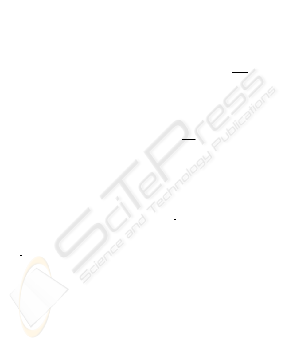
For the tests we have used an eye-in-hand camera
system composed of a JAI-M536 mini-camera in the
end-effector of a 7 d.o.f. Mitsubishi PA-10 robot
also equipped with a force sensor (67M25A-I40
from JR3. Inc.). MATROX GENESIS is used as the
image acquisition and processing board. The system
is able to acquire up to 30 frames/second and is
previously submitted to a calibration process (focal
length is 7,5 mm). In the experiments described in
this paper, the tracked target is composed of four
grey marks (see Figure 1).
Figure 1 shows the surface which the robot must
track using visual-force control (we can observe that
the surface presents a discontinuity). Applying the
sensorial fusion algorithm described in Section 4,
the evolution of the forces and of the GLR obtained
from these forces is shown in Figure 2.
Figure 1: Experimental setup
-8
-6
-4
-2
0
15913172125293337414549535761656973778185899397101105109113117121
0
500
1000
1500
2000
2500
3000
3500
1 5 9 13172125293337414549535761656973778185899397101105109113117121
Figure 2: Evolution of the force and the corresponding
GLR. Experiment 1 (convex surface)
Figure 2 show that GLR presents greater values
when the robot is not able to maintain the constant
contact with the surface. This fact can be observed
in the discontinuity of the surface.
Figure 3 and Figure 4 show two experiments for
tracking a plane surface. The first graph of each
figure represents the applied force in z direction
fusing visual and force information with constant
weights. In the second graph the proposed strategy
of variable weights is used (see Section 4). We can
observe that using the strategy of variable weights
the system response is less oscillating. Using this
strategy the system allows maintaining the constant
contact force with the surface.
-12
-10
-8
-6
-4
-2
0
1 3 5 7 9 1113151719212325272931333537394143454749515355575961636567
-12
-10
-8
-6
-4
-2
0
1 3 5 7 9 11 13 15 17 19 21 23 25 27 29 31 33 35 37 39 41 43 45 47 49 51 53 55 57 59 61 63 65 67
Figure 3: Comparison between the obtained forces without
using and using the strategy of variable weights.
Experiment 2.
-12
-10
-8
-6
-4
-2
0
1 3 5 7 9 11 13 15 17 19 21 23 25 27 29 31 33 35 37 39 41 43 45 47 49 51 53 55 57 59 61 63 65 67 69 71 73 75
-12
-10
-8
-6
-4
-2
0
1 4 7 10 13 16 19 222528 313437 40434649 525558 616467 707376
Figure 4: Comparison between the obtained forces without
using and using the strategy of variable weights.
Experiment 3
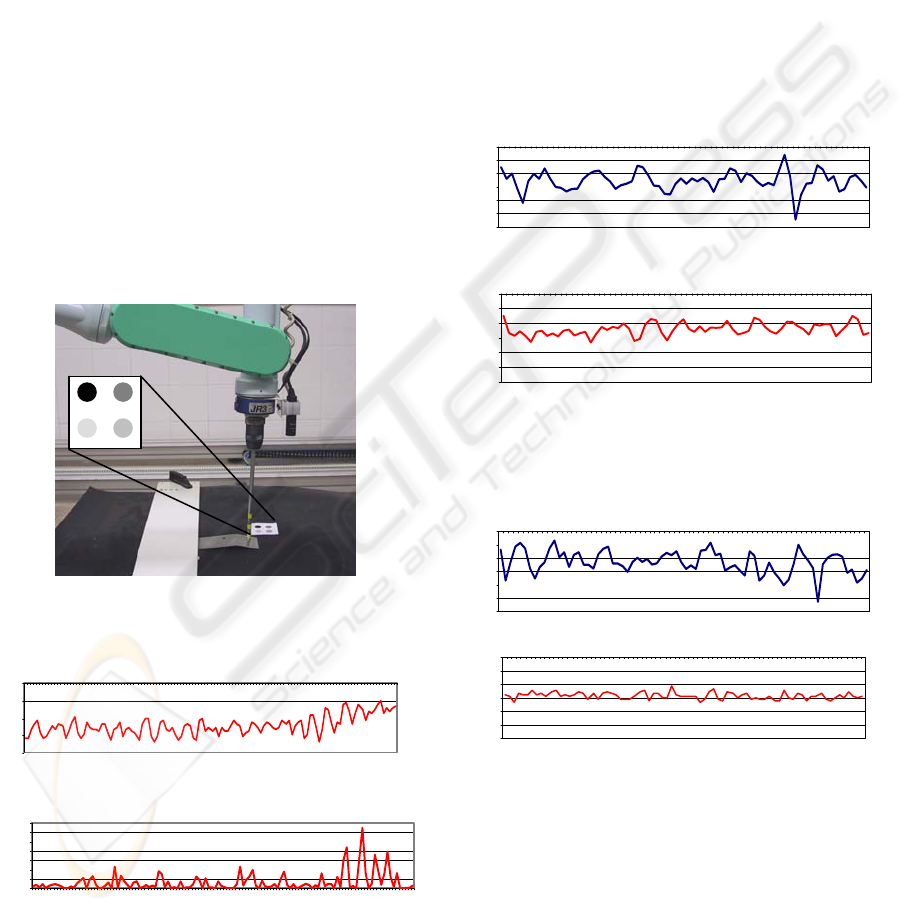
When a collision is detected the system updates
the intrinsic parameters to guarantee that the new
trajectory is generated correctly. To illustrate the
behaviour of the algorithm we show an
autocalibration experiment. Figure 5 shows the
image trajectory obtained varying the intrinsic
parameters until
I
ξ
=s-s is zero. The convergence
F
z
(N)
Iterations (with variable weights)
F
z
(N)
F
z
(N)
GLR
Iterations
Iterations
Iterations
Iterations
F
z
(N)
F
z
(N)
Iterations (with variable weights)
ICINCO 2005 - ROBOTICS AND AUTOMATION
200
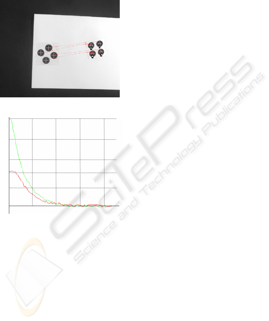
of the focal length estimations is shown in Figure 6
(the pixel is almost the same in
u and v directions on
the image sensor).
Figure 5: Image trajectory during the autocalibration
Figure 6: Convergence of the estimated focal lengths
8 CONCLUSIONS
We proposed a new method for combining visual
and force information which allow us to update the
intrinsic parameters during the task by using an
autocalibration approach. The visual-force control
system has others original aspects which improve
the behaviour of the system. Within these aspects we
should mention the variable weights applied to each
sensor (depending on the GLR parameter) and the
possibility of managing contradictory control
actions. As the results show, the robot is able to
track the image trajectory maintaining a constant
force with the workspace using visual and force
information simultaneously.
REFERENCES
Baeten, J., De Schutter, J., 2002, Hybrid Vision/Force
Control at Corners in Planar Robotic-Contour
Following. IEEE/ASME Transactions on
Mechatronics, vol. 7, no 2, pp. 143 – 151.
Baeten, J., Bruyninckx, H., De Schutter, J, 2002. Shared
Control in Hybrid Vision/Force robotic Servoing using
the Task Frame. In Proceedings of the 2002 IEEE/RSJ
International Conference on Intelligent Robots and
Systems. Lausanne, Suiza. Pp. 2128-2133.
Bruyninckx, H., De Schutter, J., 1996. Specification of
force-controlled actions in the task frame formalism-A
synthesis, IEEE Transactions on Robotics and
Automation, vol. 12, no. 4. pp. 581-589.
Hutchinson, S., Hager, G., Corke, P., 1996. A Tutorial on
Visual Servo Control. IEEE Trans. on Robotics and
Automation, vol. 12, no. 5, pp. 651-670.
Marchand, E., Chaumette, F., 2002. Virtual Visual
Servoing: a framework for real-time augmented reality.
In EUROGRAPHICS 2002 Conference Proceeding,
Computer Graphics Forum, Sarrebruck, Germany. vol.
21, no. 3, pp. 289-298.
Mezouar, Y., Chaumette, F., 2002. Path Planning For
Robust Image-based Control. IEEE Transactions on
Robotics and Automation, Vol. 18, No. 4, pp. 534-
549.
Morel, G., Malis, E., Boudet, S., 1998. Impedance based
combination of visual and force control. In IEEE Int.
Conf. on Robotics and Automation, Leuven, Belgium,
pp. 1743-1748.
Namiki, A., Nakabo, I., Ishikawa, M., 1999. High speed
grasping using visual and force feedback. In IEEE Int.
Conf. on Robotics and Automation, Detroit, MI, pp.
3195-3200.
Olsson, T., Bengtsson, J., Johansson, R., Malm, H., 2002.
Force Control and Visual Servoing Using Planar
Surface Identification, In IEEE Int. Conf. on Robotics
and Automation. Washington, USA. Pp. 4211-4216.
Pomares, J., Torres, F., 2005. Movement-flow based
visual servoing and force control fusion for
manipulation tasks in unstructured environments. IEEE
Transactions on Systems, Man, and Cybernetics—Part
C. Vol. 35, No. 1. Pp. 4 – 15.
Tsuji, T., Hiromasa, A., Kaneko, M., 1997. Non-contact
impedance control for redundant manipulators using
visual information, In IEEE Int. Conf. on Robotics and
Automation, Albuquerque, USA. vol. 3, pp. 2571-2576.
Willsky, A. S., Jones, H. L., 1976. A generalized
likelihood ration approach to the detection and
estimation of jumps in linear systems. IEEE Trans.
Automat. Contr., vol. 21, no. 1, pp. 108-112.
Zhang, Z., 2000. A flexible new technique for camera
calibration. IEEE Transactions on Pattern Analysis and
Machine Intelligence, vol. 22, no. 11, pp. 1330-1334.
8,8
8,5
8,2
8
7,8
7,5
10 20 30 40
Iterations
mm.
f
u
f
v
ADAPTIVE VISUAL-FORCE CONTROL IN UNKNOWN WORKSPACES
201
