MICROSILICON LUMINOUS FLUX SWITCH CONTROLLED
BY MEANS OF MAGNETIC FIELD
J. Gołębiowski, T. Prohuń
Institute of Theoretical Electrotechnics, Metrology and Materials Science,
Technical University of Łódź, ul.Stefanowskiego 18/22, 90-928 Łódź. POLAND
Keywords: Optical silicon switch, micro-electro-optical-mechanical system (MEOMS), magnetic transducer, FEM.
Abstract: The construction of a silicon beam which is used as a optical switch was presented. The investigated beam
consists of three layers: on the silicon base the iron layer is put and it is followed by the aluminium layer.
The change of the external magnetic field intensity causes the beam end displacement as well as the change
of the luminous flux reflection angle. The influence of the magnetic transducer parameters as well as the
field intensity on the luminous flux reflection angle are analysed. The optical system which is steered by the
magnetic field was described.
1 THE CONSTRUCTION OF THE
OPTICAL SWITCH
Microsilicon structures are commonly applied in the
sensors or actuators in which piezoelectric,
electrostatic, electromagnetic and magnetic
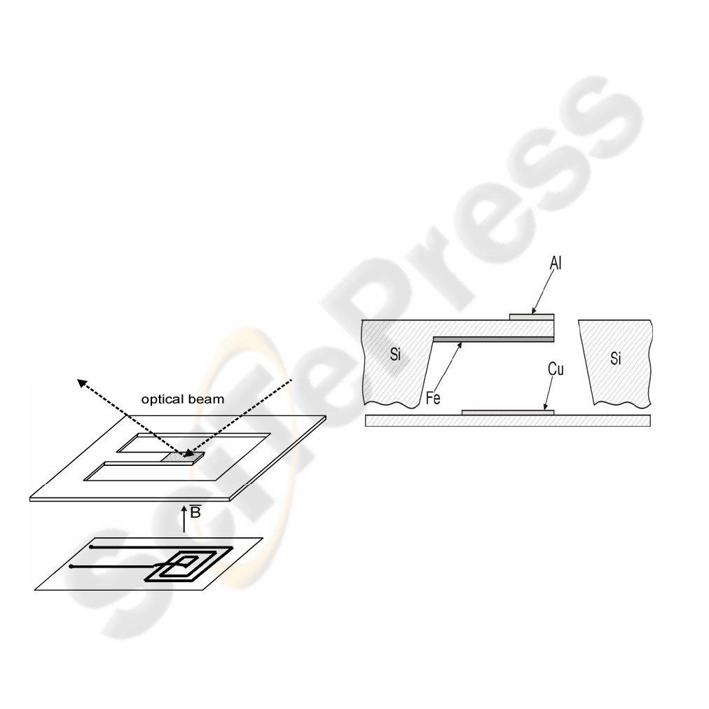
transducers are used (Ciudad, 2004). The scheme of
the magnetic transducer with the silicon microbeam
is shown in Fig.1.
Figure 1: The scheme of the magnetic transducer with the
silicon beam
The structure with the micro-mirror on the
surface (aluminium layer) can be used to the
luminous flux switching in scanners, display units as
well as in the optical path switchers for
communication (Cho, 2002).
Figure 2: The cross - section of the microstructure with
the monocrystalline silicon, Si <100>, base and the
magnetic (Fe) and metallic (Al, Cu ) layers
The beam structure we studied is shown
schematically in Figure 1 and 2 (Wagner, 1992). It
consists of a narrow silicon beam (monocrystalline
silicon <100>) with of thin magnetic layer (Fe) and
metallic layer (mirror- Al). A planar coil was used
for the magnetic field generation (Fig.1, Fig.2)
(Ripka, 2001).
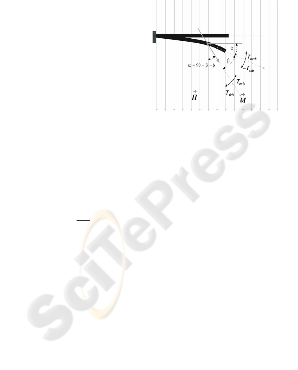
If a uniform magnetic field is applied to this
structure, a pure moment without a translational
force is induced. The pure moment or torque
generated by the magnetic transducer rotates the
beam end through an angle
φ
(Fig.3).
301
Golebiowski J. and Prohun T. (2005).
MICROSILICON LUMINOUS FLUX SWITCH CONTROLLED BY MEANS OF MAGNETIC FIELD.
In Proceedings of the Second International Conference on Informatics in Control, Automation and Robotics, pages 301-306
Copyright
c
SciTePress
2 THE ANALYSIS OF THE
LUMINOUS FLUX
REFLECTION ANGLE IN THE
TRANSDUCER CONTROLLED
BY MEANS OF THE
MAGNETIC FIELD
The beam with the thin ferromagnetic layer is
analysed.. It is assumed that the material is isotropic
and homogenous as well.
The torque generated under the influence of the
external magnetic field can be expressed as (Judy,
1997) :
α
sin⋅⋅⋅=×= HMVHMVT
field
rr
(1)
where M is magnetization vector,
α
is an angle
between the magnetization vector and the external
field intensity and V is the magnetic material
volume.
The magnetic field direction is normal to the
normal beam axis as it is shown in Fig. 3.
The torque formed at the external field H causes
the magnetization vector M rotation and the rotation
angle towards the normal beam axis is equal to
β
.
When
β
angle increases the field of the magnetic
anisotropy increases as well (Tumanski 1997)
according to the equation:
s
anis
M
K
H
⋅
=
2
(2)
where M
s
is the saturation value of the
magnetization and K is magnetic anisotropy
constant.
The anisotropic field generates the torque T
anis
which shifts the magnetization vector M towards the
beam axis.
The beam is under the influence of the torque of
opposite sense -T
anis
. As a results the beam
dislocation is observed. For the silicon beam with
the ferromagnetic layer and the elasticity coefficient
k
mech
the dislocation generates the mechanic torque
which counteracts the magnetic torque -T
anis
and is
equal to:
φ
⋅
−
=
mechmech
kT (3)
At the equilibrium state the absolute values of
torques are equal.
Figure 3: The beam deflection under the influence of the
magnetic field H. (Judy, 1996)
The investigated beam consists of three layers:
monocrystalline silicon, iron and aluminium.
The analysis is carried out basing on the
following assumptions:
For the crystallographic orientation <100>
silicon is an orthotropic material with:
Young’s modulus E = 1.31*10
11
N/m
2
,
Poisson ratio
ν
= 0.0625,
Density
ρ
= 2330kg/m
3
.
The iron layer parameters are equal to:
Young’s modulus E = 2*10
11
N/m
2
,
Poisson ratio
ν
= 0.29,
Density
ρ
= 7870kg/m
3
.
The aluminium layer parameters are equal to:
Young’s modulus E = 0.7*10
11
N/m
2
,
Poisson ratio
ν
= 0.33,
Density
ρ
= 2700kg/m
3
.
The model allows to create the dislocation net
which reflects the influence of the external magnetic
field on the transducer magnetic layer.
At first the density of magnetic energy
accumulated in the ferromagnetic layer is calculated.
It consists of the external magnetic field energy and
the energy of the magnetic anisotropy field. The
value of the accumulated energy is used to the
determination of the force which influences the
beam and causes its displacement.
Regarding the existence of ferromagnetic layer
anisotropy the finite element and the coupling field
methods as well as FEMLAB program are used in
the calculations.
As the FEMLAB programme uses the coupling
field method it is possible to take into accounts a
variety of physical phenomena and their interactions.
The finite element method MES allows to simulate
the miscellaneous mechanical structures including
ICINCO 2005 - INTELLIGENT CONTROL SYSTEMS AND OPTIMIZATION
302
the silicone ones (Lam, 2001). The investigated
beam has got an elastic silicon layer and
ferromagnetic iron layer.
The analysed structure is divided into 20 000
elements, and the generated net has got 120 000
nodes. The material anisotropy is also taken into
considerations.
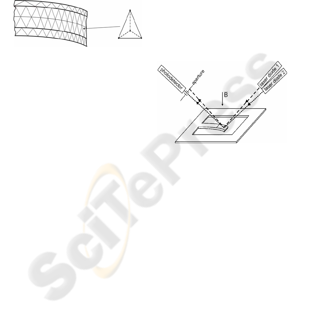
Figure 4: The partition of the structure and an elementary
tetrahedron
The elementary tetrahedrons were taken into
accounts in the FEMLAB programme calculations
(Fig.4). The starting point for the finite element method
is a mesh, a partition of the geometry into small units of
a simple shape.
In 2D, the method partitions the subdomains into
triangles, or mesh elements. The boundaries defined in
the geometry are partitioned (approximately) into
mesh edges (so-called boundary elements) that must
conform with the triangles if there is an adjacent
subdomain.
In 3D the method partitions subdomains into
tetrahedrons. It partitions boundaries in the geometry
into triangular boundary elements; and the isolated
geometry vertices become mesh vertices (node points).
The size of the elements and their number were
selected according to the parted structure size and
the assumed boundary conditions.
Then, for the parted structure, the subsequent
approximations of the searched variable were made.
The idea is to approximate variable with a function
which could describe with a finite number of
parameters, the so-called degrees of freedom (DOF).
Inserting this approximation into the weak form of the
equation generates a system of equations for the
degrees of freedom.
3 THE OPTICAL MICROSWITCH
SYSTEM
The optical method was applied to measure the
placement of the beam end arm. As a light source 2
laser diodes were used. The light ray reflected from
the mirror (aluminium layer) incidence on the
photodiode.
The change of the beam deflection angle causes
the change of the luminous flux reflection angle. The
propriety was used in the construction of the
luminous flux switch system. The aluminium layer
reflect the rays of both laser diodes, but, for the
particular beam arm placement, only one of them
reflects at the proper angle. Then the ray goes
through the apreture and is received by photodiode.
The flux from the other laser diode is reflected by
the beam mirror and does not fall on the photo
detector. The particular beam arm placement allows
to receive only one optical flux.
The beam arm placement steering is achieved by
the change of the current value in the coil that
generates the magnetic field.
The change of the magnetic field induction
changes the force which affects the beam arm and
the angle of the beam deflection as well.
Figure 5: The principle of the optical switch work.
4 RESULTS
The analysis of the beam size influence on the beam
end displacement and the angle for the assumed
magnetic induction was carried out. According to
the technological requirements the maximum
allowable beam size changes were assumed and the
influence of these parameters on the angle
φ
was
analysed.
The analysis of the influence of the beam end
parameters on the displacement at the given and
equal to B=10mT generated magnetic field
induction was carried out. The following model
parameters were taken into accounts: the lenght
l=5mm, the layer thicknesses 20µm, 10µm and 1µm
for the silicon, iron and aluminium layer
respectively.
MICROSILICON LUMINOUS FLUX SWITCH CONTROLLED BY MEANS OF MAGNETIC FIELD
303
5,00E-03
5,10E-03
5,20E-03
5,30E-03
5,40E-03
5,50E-03
5,60E-03
5,70E-03
5,80E-03
5,90E-03
6,00E-03
00,511,522,5
w - width (mm)
z - displacement (mm)
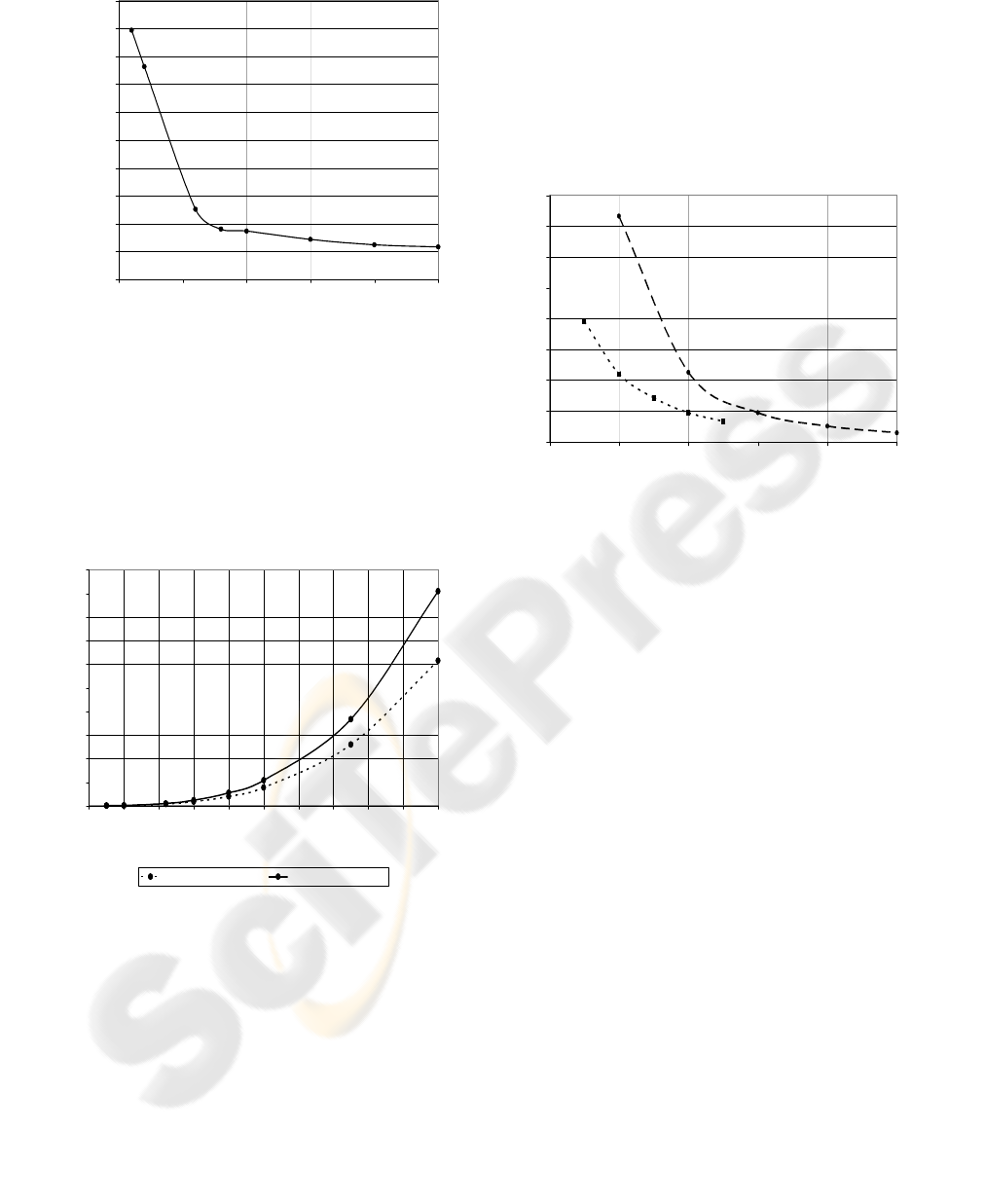
Figure 6: The dependence of the beam end displacement
on the beam width w for B=10mT, l= 5mm and d=31µm
For the assumed model the calculations of the
influence of the beam width on its displacement
were performed. (Fig.6). The beam lenght was
l=5mm, and the thicknesses of the layers were
20µm, 10 µm and 1 µm for silicon, iron and
aluminium layer respectively.
0
0,1
0,2
0,3
0,4
0,5
0,6
0,7
0,8
0,9
1
012345678910
l - length (mm)
- an
g
le
(
de
g
.
)
analytical calculation simulation FEMLAB
φ
Figure 7: The influence of beam lengths on the angle of its
deflection (w=1.5mm, d=31µm, B=10mT).
Fig.7 presents the displacement of the beam end for
the different beam lenghts.
According to Judy’s (Judy 1996) model the
analytical calculations of the beam deflection angle
generated by external magnetic field were carried
out. The comparison of the calculated results and the
data of the FEMLAB program simulation are
presented in Fig. 7. As it can be seen the results are
in fairly good agreement. The inconsiderable
discrepancies are due to the simplifications assumed
for the analytical calculations and the material data
as well.
In order to maximalize the dislocation the
influence of the layer thicknesses was also analysed.
In the calculations the following values were
applied: l=5mm, w=1.5mm, d
Si
=20µm, d
Fe
=10µm,
d
Al
=1µm.
0
0,05
0,1
0,15
0,2
0,25
0,3
0,35
0,4
0 1020304050
d - thickness (um)
- an
g
le
(
de
g
.
)
Si
Fe
φ
Figure 8: The influence of the layer thickness on the angle
of the beam deflection (l=5mm, w=1,5mm, B=10mT).
Fig.8 shows the beam displacement as a function of
the thickness of the particular layers.
‘Si’ characteristic presents the influence of the
silicon layer thickness for the assumed thicknesses
of the others layers which were equal to d
Fe
=10µm,
d
Al
=1µm.
‘Fe’ characteristic presents the dependence of the
iron layer thickness for the assumed thicknesses of
silicon d
Si
=20µm and aluminium d
Al
=1µm layers.
The silicon layer thickness was analyzed in the
range of 10µm – 50µm. It is an elastic layer of the
base on which transducer was constructed.
The iron layer is a ferromagnetic layer and its
thickness can be matched to the field intensity range
as well as to the assumed beam displacement.
The aluminium layer is a mirror that is used to
measure the beam displacement by means of the
optical method. That is why is should be as thin as
possible in order not to increase the beam mass.
The influence of the aluminium layer thickness is
insignificant and can be omitted.
ICINCO 2005 - INTELLIGENT CONTROL SYSTEMS AND OPTIMIZATION
304
0
0,5
1
1,5
2
2,5
3
3,5
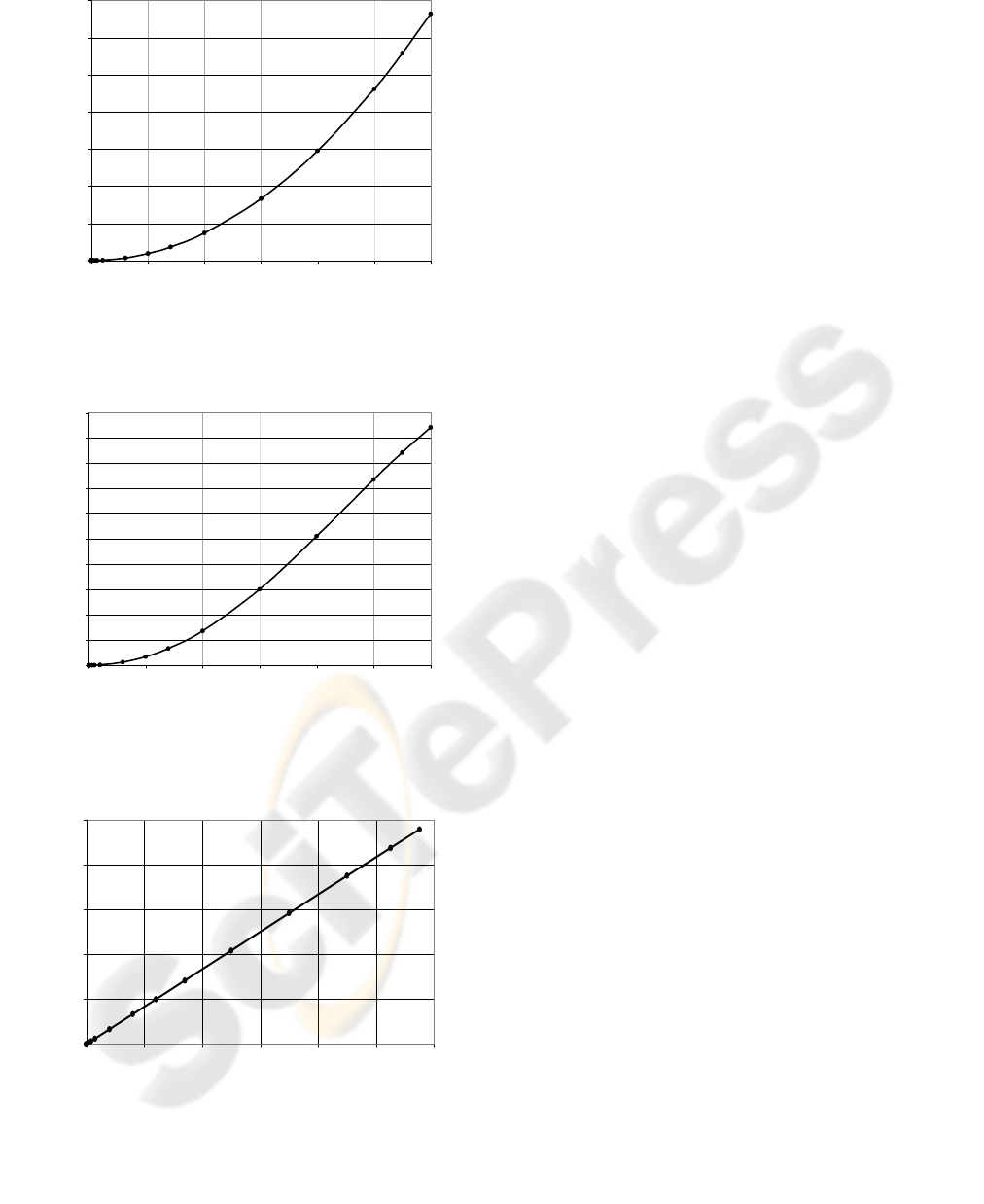
0 0,005 0,01 0,015 0,02 0,025 0,03
B - magnetic flux density (T)
- angle (deg.)
φ
Figure 9: The angular deflection of the beam on magnetic
flux density B
(l=5mm; w=0,5mm; d
Si
=15µm, d
Fe
=5µm, d
Al
=1µm)
0
5
10
15
20
25
30
35
40
45
50
0 0,005 0,01 0,015 0,02 0,025 0,03
B - magnetic flux density (T)
- angle (deg.)
φ
Figure 10: The angular deflection of the beam on
magnetic flux density B
(l=10mm; w=1mm; d
Si
=10µm, d
Fe
=5µm, d
Al
=1µm)
0
0,4
0,8
1,2
1,6
2
0 0,005 0,01 0,015 0,02 0,025 0,03
B - magnetic flux density (T)
S
B
- sensitivit
y
Figure 11: The sensivity coefficient as a function of
magnetic flux density B
(l=5mm; w=0,5mm; d
Si
=15µm, d
Fe
=5µm, d
Al
=1µm)
Figs.9 and 10 present the influence of the
angular
deflection of the beam o
n the magnetic flux density B.
5 CONCLUSIONS
The analysis of the influence of beam size on its
displacement leads to the following conclusions:
-The maximum sensitivity coefficient
S
w
=0.0125deg./mm (S
w
=
∆φ
/
∆
w) was observed for
the beam width in the range 0.1mm – 0.6mm, (for
l=5mm, d=31µm, B=10mT),
-The maximum sensitivity coefficient
S
l
=0.217deg./mm (S
l
=
∆φ
/
∆
l) was obtained for the
beam length in the range of 7,5mm – 10mm, (for
w=1.5mm, d=31µm and B=10mT).
According to the expectations the maximum
displacements were obtained for the beams with the
maximum length (10mm) and minimum width
(0.1mm).
The analysis of the influence of the particular layer
thickness on the sensitivity coefficients leads to the
following statements:
-The maximum sensitivity coefficient
S
dSi
=0.0254deg./µm was observed for the silicon
layer thickness in the range of 10µm – 20µm,
-The maximum sensitivity coefficient
S
dFe
=0.0171deg./µm was obtained for the thickness
in the range of 5µm – 10µm.
The aluminium layer is a mirror and its thickness is
a requisite of the technological conditions. The most
commonly the aluminium layer thickness is in the
range of 0.5µm – 1µm. The layer only slightly
influences the beam displacement.
The function of the angle changes depending on the
magnetic field induction values is shown in Fig.9.
The change of the external magnetic field induction
in the range of 100µT – 30mT causes the
displacement change from 1.7nm to 0.156mm. The
maximum sensitivity coefficient s
B
=1.67
(s
b
=(
∆φ
/
φ
)/(
∆
B/B)) was obtained for induction in the
range 20mT – 30mT, whereas for the range of
100µT – 1mT the coefficient is equal to s
B
=0.037.
For the generated field induction B=30mT the beam
displacement equal to 3.30 deg. was achieved.
The usage of the presented beam as a steering
element needs to acquire the beam deflection angle
as high as possible. It can be carried into effect by
beam elongation. (Fig.10. The beam lenght is equal
to l=10mm, its width w=1mm and its thickness
d=16µm, B=30mT,
φ
=47deg.). The beam deflection
angle can also be maximalized by narrowing of the
beam fore - part and by enlarging of the magnetic
material mass (which is used only in the beam end -
part).
MICROSILICON LUMINOUS FLUX SWITCH CONTROLLED BY MEANS OF MAGNETIC FIELD
305

REFERENCES
Ahn C. H., Kim Y. J., Allen M. G., 1993. A planar variable
reluctance magnetic micromotor with fully integrated
stator and wrapped coils. Proceedings of IEEE Micro
Electro Mechanical Systems (MEMS '93), pp. 1-6.
Bosch D., Heimhofer B., Muck G., Seidel H., Thumser U.,
and Welser W., 1993. A silicon microvalve with
combined electromagnetic/electrostatic actuation.
Sensors and Actuators A, v. A37-A38, pp. 684-692.
Cho H.J., Ahn C.H., 2002. A bidirectional magnetic
microactuator using electroplated permanent magntet
arrays. J., Microelectromech. Syst. 11, pp. 78-84.
Ciudad D., Aroca C., Sanchez M.C., Lopez E., Sanchez P.,
2004. Modelling and fabrication of a MEMS
magnetostatic magnetic sensor. Elsevier Sensors and
Actuators, A 115, pp. 408-416.
Cullity B.D., 1972. Introduction to magnetic Materials.
MA: Addison-Wesley, p. 527.
Gołębiowski J., Prohuń T., Rybak M., 2004. Modelling of
the Silicon Membrane Vibrations Generated by Means
of Electromagnetic Forces. WSEAS Transaction on
Systems, Issue 7, vol.3, pp.2538-2540.
Gołębiowski J., 2001. Modelling of measurement
microsystems with membranes of silicone ultrasonic
sensors. Proc. of 2001 WSES/IEEE Intern. Conference
on Simulation S IM’01/IEEE, Malta, pp.87-90.
Guckel H., Christenson T. R., Skrobis H. J., Jung T. S.,
Klein J., Hartojo K. V, Widjaja I., 1993. A first
functional current excited planar rotational magnetic
micromotor. Proceedings of IEEE Micro Electro
Mechanical Systems (MEMS '93), pp. 1-6.
Irons H.R. Schwee L.J., 1972. Magnetic thin-film
magnetometers for magnetic field measurement. IEEE
Trans. Magn. Vol. 8, pp. 61-65.
Judy J.W., Muller R.S., 1996. Magnetic Microactuation of
Torsional Polysilicon Structures. Sensors and
Actuators A, v. A53, no. 1-3, pp. 392-397.
Judy J.W., Muller R.S., 1996. Batch-Fabricated,
Addressable, Magnetically Actuated Microstructures.
Tech. Dig. Solid-State Sensor and Actuator Workshop,
pp. 187-190.
Judy J.W., Muller R.S., 1997. Magnetically Actuated,
Addressable Microstructures. Journal of
Microelectromechanical Systems, vol. 6, no. 3, pp.
249-256.
Konno H., 1991. Integrated ferromagnetic MR sensors. J.
Appl. Phys., vol. 69, pp 5933-5935.
Lachowicz H., 1995. Nowe materiały i zjawiska
magnetyczne. Elektronika, vol. 36, pp. 12-17.
Lam T., Darling R.B., 2001. Psychical Modelling of
MEMS Cantilever Beams and the Measurement of
Stiction Force, Modelling and Simulation of
Microsystems. ISBN 0-9708275-0-4, pp. 418-421.
Liao S., 1990.
Electrodeposition of magnetic materials for
thin-film heads. IEEE Transactions on Magnetics, vol.
26 no.1 pp. 328-332.
Ripka P., 2001. Magnetic Sensors and Magnetometers.
Artech House Inc., pp. 381-382.
Roark R.J., 1989. Roark’s Formulas for Stress and Strain.
6
th
Edition, Warren C. Young Editor, New York,
McGraw-Hill Book Co.
Tang W C., Nguyen T.-C.H., Judy M. W., Howe R. T.,
1990. Electrostatic-comb drive of lateral polysilicon
resonators. Sensors and Actuators A, v. A21, no. 1-3,
pp. 328-331.
Timoshenko S.P., Goodier J.N., 1970. Theory of
Elasticity. 3
rd
Edition, New York, McGraw-Hill Book
Co.
Tumański S., 1997. Cienkowarstwowe czujniki
magnetorezystancyjne. Oficyna Wydawnicza
Politechniki Warszawskiej.
Tumański S. 1985. Współczesne metody pomiaru słabych
pól magnetycznych. Prace Naukowe Politechniki
Świętokrzyskiej, vol. 16, pp. 81-95.
Wagner B., Benecke W., Engelmann G., Simon I., 1992.
Microactuators with moving magnets for linear,
torsial, or multiaxial motion. Sensors and Actuators A
(Physical), v. A32, no. 1-3, pp. 598-603.
ICINCO 2005 - INTELLIGENT CONTROL SYSTEMS AND OPTIMIZATION
306
