
INTELLIGENT ROBOTIC PERSON FOLLOWING IN
UNSTRUCTURED ENVIRONMENTS
Mahmoud Tarokh and John Kuo
Department of Computer Science, San Diego State University, San Diego, CA 92124, U.S.A.
Keywords: Robotic person following, fuzzy control, image recognition.
Abstract: The paper describes a scheme based on image identification and fuzzy logic control for following a person
by a mobile robot in previously unknown and rough environments. The mobile robot is equipped with a
pan-tilt-zoom camera and sonar range sensors. The person detection system uses color and shape of the
person to be followed, and provides key characteristics of the person’s image to a fuzzy control scheme.
These characteristics are used by fuzzy controllers to determine the actuation signals for the camera pan and
tilt, and the robot speed and steering. Experimental results are reported for both indoor locations consisting
of tours of labs and hallway, and outdoor environments involving traversal over hills and rough terrain.
1 INTRODUCTION
Vision based robotic tracking and following persons
has many applications such as surveillance, motion
capture and human assistance. The major
requirement in these applications is the ability to
track and follow a moving person through non-
predetermined, unstructured and often rough
environments. The robotic person following
consists of two main tasks - person recognition and
segmentation from the surrounding environment,
and motion control to follow the person using the
recognition results.
Frame differencing, which compares
consecutive image frames, is the simplest and fastest
algorithm for detecting moving objects, especially
when the camera is static (Cai 1995, Richards
1995). However, the major challenge in the tracking
task is the detection of person’s motion by a camera
mounted on a moving robot as these two motions
are blended together. A number of approaches have
been proposed to address this issue, e.g. tracking
features (Censi 1999, Zoghlami 1997, Foresti 2003)
and computing optical flow (Srinivasan 1997, Irani
1994). In (van Leeuwen 2002) a method is
proposed to track cars in front using a camera
mounted on the pursuing car. A color based tracking
system capable of tracking color blobs in real time
is implemented on a mobile robot (Schlegel 2000),
but requires the person to wear a shirt of specified
color and does not consider shape. An approach to
recognition of a moving person by a camera
mounted on a robot is provided in (Tanawongsuwan
1999) which also uses color recognition. These
approaches are only effective in environments that
do not contain objects whose color is similar to that
of the person to be tracked. More recently, a
probabilistic approach is proposed which is based
on frame differencing with a compensation for the
robot mounted camera motion (Jung 2004)
There has also been considerable work in the
area of autonomous robot navigation, but very few
addressing person following. In particular
numerous fuzzy-logic base approaches have been
developed for navigation (e.g. see Saffiotti 1997 for
a review). Fuzzy logic has been applied to the wall
following and obstacle avoidance problem
(Braunstingl 1995). Omni-directional cameras,
although expensive, are useful in sensing motion in
every direction (Gasper 2000). Such cameras allow
creation of panoramic images of the environment,
which can be used for navigation and control of a
mobile robot. Research reported in (Weng 1998)
uses vision to guide a mobile robot by comparing
images to a database of images that are created
during an initialization tour of the environment.
Regardless of the approach, navigation and tracking
using maps require that the environment be known
prior to application, which limits flexibility and is
not a valid approach to person following.
A simple vision based robotic person following
was recently proposed for flat environments using a
gray-scale camera that was fixed to a mobile robot
101
Tarokh M. and Kuo J. (2005).
INTELLIGENT ROBOTIC PERSON FOLLOWING IN UNSTRUCTURED ENVIRONMENTS.
In Proceedings of the Second International Conference on Informatics in Control, Automation and Robotics - Robotics and Automation, pages 101-106
DOI: 10.5220/0001166601010106
Copyright
c
SciTePress

platform (Tarokh 2003). The purpose of the present
paper is to enable robust person following in rough
terrain. In this work we employ color and shape for
person identification and pan/tilt camera control for
robust person tracking
2 TRAINING AND DETECTION
The first task in person following is the detection
and segmentation of the person from the scene.
This task consists of two subtasks, namely, training
a detection system and recognition of the person as
he/she moves in the environment. Both these
subtasks employ color and shape characteristics.
In our system, the person appears in front of the
camera at the start of a tour, and images of the
person are captured automatically when the person
takes several poses, i.e. back to camera, and side
view. The system is then trained to recognize the
shape and color of the person’s upper body. We use
H (hue or color), S (saturation or color depth), B
(brightness or lightness) color model, as HSB is
based on direct interpretation of colors and provides
a better characterization compared to other color
models such as RGB for this application. The
averages of H, S and B components for the poses
are recorded, which provide the nominal values
,H
nom nom
S and
nom
B . However since these
values will go through changes during the motion,
we allow deviations
H∆ , S
∆
, B∆ from the nominal
values, which are found experimentally. Thus
during the person following, if an object in the
image has color components within the reference
values
),HHH(
nomref
∆
±= )SSS(
nomref
∆
±
=
and
)BB(B
nomref
∆±= , then the object will be a
candidate for the person’s image, and its shape
measures are checked.
We train the shape identification system with
the above mentioned poses. Shape measures must be
independent of the mass (area) of the person’s image
since the mass changes with the distance of the robot
to the person. The three measures that satisfy this
requirement are compactness C, circularity Q and
eccentricity E. Equations for computing these shape
measures are given in (Tarokh 2003), where the
normalized values of the three measures are between
0 and 1. During the training, each of these
measures is evaluated for the person in each of the
above two poses (k = 1,2) and their values
refk,
C
,
ref,k
Q and
ref,k
E are stored for the person
following phase. This completes the training of the
system, which takes a few seconds on a standard PC,
and can be considered as an off-line phase.
During person following, the camera takes
images of the scene and the system performs several
operations to segment the person from other objects.
The first operation is to scan every pixel and mark
the pixel as belonging to the person image, e.g. set it
is to white if all its three color components are
within the reference color ranges
ref
H ,
ref
S and
ref
B . This process of checking all pixels is time
consuming, and therefore we speed it up by
considering two observations. First, since the
person’s image occupies a large portion of the
image, it will be sufficient to check pixels on every
other row and every other column for color
verification. This way only a quarter of the pixels
are checked and marked white if they satisfy the
color range. The skipped pixels will be marked
white if the checked pixels around them have been
marked white. The second observation is that there
is a maximum distance that the person can move
between two consecutive frames. As a result, the
person’s pixels in the current frame must all lie
within a circle centered at the centroid (to be defined
shortly) of the previous frame. These two
observations limit the number of pixels to be
checked and speed up the marking of the pixels that
belong to the person’s image.
The final operation is to perform a standard
region growing on the marked pixels so that
connected regions can be formed. Regions smaller in
area than a specified value are considered noise and
are removed. The shape measures values
i
C ,
i
Q
and
i
E for the remaining regions are computed,
where i = 0,1,2,…,m-1 denote the region numbers.
Rather than checking each shape parameter with its
corresponding reference value, we define a single
measure for the closeness of the detected region to
the reference region, i.e. the person’s image during
the training. A possible function
σ
is given in
Tarokh (2003).
The closeness function produces 1 if all shape
measures of the region are the same as the reference
value, and approaches zero if the region shape
measures are completely different. It is noted that for
each detected region, two shape measures are found,
i.e. one for each pose. The region that has the
largest value of closeness
σ
is selected, and if this
value is close to 1, the selected region is assumed to
represent the person. If all the regions have small
values of
σ
, then none is chosen and another image
is taken and analyzed.
The above method of distinguishing the region
corresponding to the person from other detected
regions in the image is simple and yet quite
effective. There are several reasons for this
effectiveness. One is that the robot is controlled
reasonably close to the person being followed and in
ICINCO 2005 - ROBOTICS AND AUTOMATION
102
the direction of person’s motion, as will be seen in
the next section. This allows only few objects in the
camera’s view making the person identification
reasonably easy. Furthermore, the simplicity of
image processing tasks allows fast computation,
making it possible to achieve relatively high sample
rates.
We must now determine several characteristics
of the detected region representing the person in the
image. These characteristics will be used for the
robot control. The area or the mass of the region is
important since it gives a measure as to how close
the person is to the camera mounted on the robot. A
large mass is indicative of a person that is close to
the camera, whereas a small mass implies that the
person is far away. The mass (area) M is simply
equal to the total number of pixels in the region.
The coordinates of the center of the mass, denoted
by
cc
y,x is defined as
pq pq
cc
x
0y 0 x 0y 0
11
x
y; y x
MM
== ==
==
∑∑ ∑∑
(1)
where x, y is the coordinates of a pixel in the region,
p is the number of rows and q is the number of
columns of the image. It is noted that we assign the
x-axis across the filed of camera view, and the y-
axis along the field of view, i.e. along the path of the
person. The center of mass is of importance for
person tracking because it provides the coordinates
of the point to be tracked by the robot.
3 FUZZY FOLLOWING
CONTROL
The objective of the robot control is to follow the
person and keep a reasonably constant distance to
him/her. Since there are ambiguities and imprecision
in the image information, we propose to use a fuzzy
control paradigm. The image information, namely
the person’s mass M, the center of the mass
(
cc
y,x ) and their derivatives (
cc
y,x
&&
), are the
sensed/computed quantities. Note that the derivative
(e.g.
c
x
&
) is computed as a change in the quantity
between two samples (e.g.
c
x∆ ) divided by the
sample time, which is taken as the unit time. Thus
in what follows, we use the derivative and the
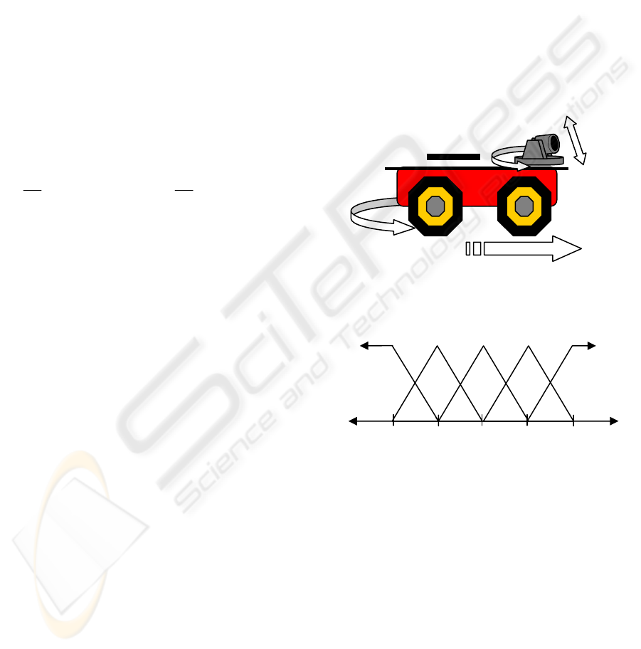
difference interchangeably. There are four
actuation quantities, as shown in Fig. 1. These are
camera pan or yaw angle
β
, camera tilt or pitch
angle
θ , robot forward/backward speed v, and robot
steering angle
ϕ . For reasons that will become
clear shortly, instead of the current values
β
,
θ
and
ϕ
, the changes to these quantities from the last
values, i.e.
β
∆
,
θ
∆
and ϕ
∆
are implemented.
Each of the sensed and actuation quantities is
treated as a fuzzy (linguistic) variable with five
normalized membership function as given in Fig 2.
The steering is not included in this table, and it value
will be determined using the average of the camera
pan (yaw), as will be described later. The fuzzy sets
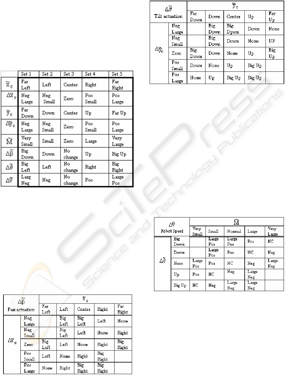
Set 1, Set 2,…, Set 5 are given specific names for
each fuzzy variable as listed in Table 1, where the
fuzzy variables are shown with a tilde. For example,
the fuzzy sets for the x-axis of the center of the mass
fuzzy variable
c
x
~
that describes motion across the
field of view of the camera are named Far Left,
Center, etc. Similarly, the fuzzy sets for the y-axis
of the mass are called Down, Up, etc. depending
where the person appears in the image.
Figure 1: Robot actuation quantities
Figure 2: Normalized membership function
Each of the sensed and actuation quantities is
treated as a fuzzy (linguistic) variable with five
normalized membership function as given in Fig 2.
The steering is not included in this table, and it value
will be determined using the average of the camera
pan (yaw), as will be described later. The fuzzy sets
Set 1, Set 2,…, Set 5 are given specific names for
each fuzzy variable as listed in Table 1, where the
fuzzy variables are shown with a tilde. For example,
the fuzzy sets for the x-axis of the center of the mass
fuzzy variable
c
x
~
that describes motion across the
field of view of the camera are named Far Left,
Center, etc. Similarly, the fuzzy sets for the y-axis
of the mass are called Down, Up, etc. depending
where the person appears in the image.
-0.5 0.5 -1.0 1.00
Set 5
Set 4
Set 2
Set 1
Set 3
φ
V
β
θ
INTELLIGENT ROBOTIC PERSON FOLLOWING IN UNSTRUCTURED ENVIRONMENTS
103
We propose the following scheme that
decomposes the control task into three controllers
for pan, tilt and speed. Steering control will be
discussed later. The main tasks of the camera pan
and tilt controllers are to position the camera so that
the person is in the camera’s sight from which the
person’s whereabouts can be deduced. The purpose
of the robot speed controller is to keep a nearly
constant distance between the robot and the person.
Table 1: Definition of fuzzy variables and associated sets
Neg = Negative, Pos = Positive
Consider first the pan (yaw) controller. When
the person moves to the left, the image of the person
will be shifted to the left of the frame along the
image x-axis if the camera and the robot are
stationary. Thus the person’s center of mass in x-
direction,
c
x , is an indication of the location of the
person across the field of view. Furthermore,
)1k(x)k(xx
ccc
−−=∆ gives the amount and
direction of the change from the last sample, where
k denotes the current sample (frame) value and (k-1)
denotes the previous value of
c
x .
Table 2: Fuzzy rule matrix for camera pan control
Table 3: Fuzzy rule matrix for tilt control
The speed controller takes two inputs, namely the
person’s image mass M and the change in the
camera tilt
θ
∆
. The mass is a measure of the
person’s distance to the camera and the larger this
mass, the closer the person will be to the camera,
and vice versa. The tilt is used to account for hilly
terrain When
θ
∆
is positive as in the case of the
person starting to climb a hill, the robot must slow
down and when
θ
∆
is negative, as in the case of the
person starting to descend a hill, it must speed up.
These considerations lead to the rule matrix given in
Table 4.
The center of gravity defuzzification is used to
determine the crisp value of the camera pan and tile,
and robot speed. The final control quantity is the
steering.
Table 4: Fuzzy rule matrix for speed control
Although it is possible to employ fuzzy rules for
determining the steering control similar to the other
three quantities, it is simpler and more reasonable to
base the robot steering on the pan (yaw) of the
camera. This is due to the observation that the
camera rotates to keep the person in its view and
thus essentially follows the person’s turning
motions, which must eventually cause the rotation
(steering) of the robot. However, it will be
unnecessary and undesirable to steer the robot at the
same rate as the camera pan. In other words, the
camera must track relatively fast and fine motions of
ICINCO 2005 - ROBOTICS AND AUTOMATION
104
the person, whereas the robot must follows the gross
motion of the person which is the average motion
taken over a time period. As a result of this
averaging, the steering is computed as
∫
θ=ϕ
dtK where K is the proportionality constant.
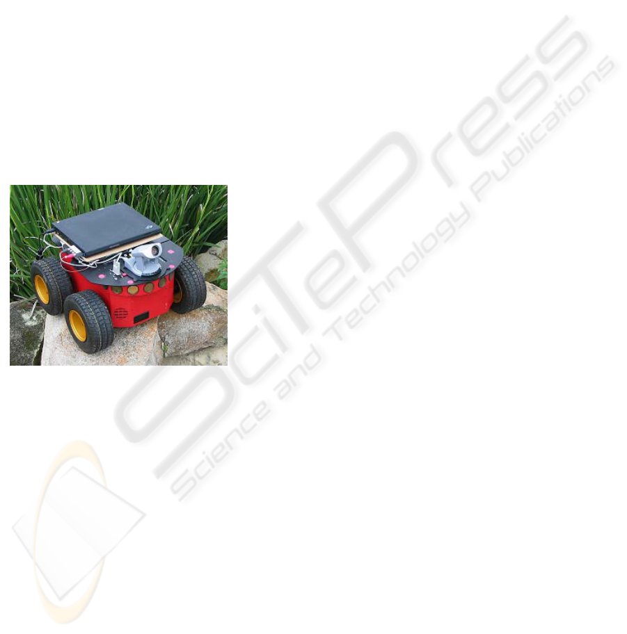
4 EXPERIMENTAL RESULTS
The robot base used in the experiments was an
ActiveMedia Pioneer2 All-Terrain rover, as shown
in Fig. 3. The base dimensions are
cm264950
×
× ,
has four motorized wheels, and can travel at a top
speed of 1.6 m/s. The Pioneer 2 is capable of
holding 40 kg and has a battery life of 10-12 hours.
The robot has a sonar ring with 8 sensors, which has
an operation range of 15 cm to 7 m. The sonar
sensors, seen in Fig. 3 as circles, are used for
obstacle detection. In case obstacles are detected, a
collision avoidance maneuvering, not described in
this paper takes place.
Figure 3: The rover used on experiments
A Cannon VC-C4 camera installed on the Pioneer
2 (Fig. 3), and permits color image capture at
maximum resolution of 640 horizontal lines and 480
vertical lines in the NTSC format. It is connected to
a laptop computer through an Imperx VCE-B5A01
PCMCIA frame gabber, which is specifically
designed for laptops. The frame grabber can achieve
capture rates of 30 frames/second at the lowest
resolution of
120160× in NTSC format, and 5
frames per second at the highest resolution of
480640× . The laptop mounted on the base (Fig. 3)
is an IBM T40 with Windows XP operating system.
It contains an Intel Centrino processor running at 1.5
MHz.
The application uses a variety of software
libraries written by third-party for creating interface
and enabling device control. The libraries for the
user interface are written in Java, whereas libraries
for low motor control are in C++. As a result our
person following code was written both in Java and
C++. The person following application uses the
client server, distributed callback, model view
controller. The cycle (sample) time for performing
various tasks is found to be 0.13 s, or about 8
Extensive indoor and outdoor trials were
conducted with the person following system. Indoor
trials included passing through a door (Fig. 4), and
identification of person to be followed amongst
several persons. Outdoor trials included following
up a steep and winding dirt trail (Fig. 5), a rocky
terrain (Fig. 6) that involved shaking of the rover,
and following with incomplete image and partial
occlusion (Fig. 7).
The successful experiments in rough terrain and
partial occlusion, demonstrate that the person
detection and fuzzy controllers are able to cope with
shaky images and imprecise or incomplete
information. The system even handle full occlusion
in cases where the person does not quickly change
directions or disappear behind other objects for an
extended period of time.
5 CONCLUSIONS
The paper has presented an intelligent based control
method for person following in previously unknown
environments. It consists of a simple person
identification using both color and shape, and fuzzy
controllers for the camera and the robot. It is shown
through various experiments that the system can
function in both indoors and outdoors. The system
has a number of features, which include robustness
to noise due to rough terrain traversal, and to partial
occlusion. It can perform well in difficult locations
such as hallways with tight turns, and winding hilly
outdoor trails. A video showing person following in
various environments has been prepared and will be
shown at the conference.
The system has two limitations. First, it is unable
to perform satisfactory person following when the
person moves fast. The main bottlenecks are image
capture/save and thresholding routine that in
combination take more than half of the total cycle.
The other limitation is that in bright outdoor lights
with distinct shadows, the person identification
system can get confused since it treats the shadows
as objects/obstacles. We are currently investigating
these issues to improve the robustness of the system.
INTELLIGENT ROBOTIC PERSON FOLLOWING IN UNSTRUCTURED ENVIRONMENTS
105
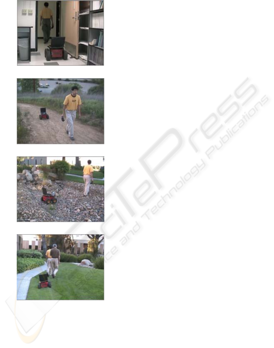
Figure 4: Passage through a door
Figure 5: Following a steep dirt trail
Figure 6: Traversing rough terrain
Figure 7: Coping with partial occlusion
REFERENCES
Braunstingl, R., Sanz, P., and Ezkerra, J. M. 1995. Fuzzy
logic wall following of a mobile robot based on the
concept of general perception, Proc. 7th Int. Conf. on
Advanced Robotics
, pp. 367-376, Spain.
Cai, Q., A. Mitchie and J. K. Aggrarwal
,1995. Tracking
human motion in an indoor environment,
2
nd
Int. Conf.
on Image Processing
Censi, A., A. Fusiello, and V. Roberto, 1999. Image
stabilization by feature tracking,
Proc. 10
th
Int. Conf.
Image Analysis and Processing,
pp. 665-667, Venice,
Italy.
Foresti, G. L. and C. Micheloni, 2003. A robust feature
tracker for active surveilance of outdoor scenes,
Electronic Letters on Computer Vision and Image
Analysis,
vol 1, No. 1, 21-34.
Gaspar, J., N. Winters and J. Santos-Victor, 2000. Vision-
based navigation and environmental representation
with omni-directional camera,
IEEE Trans. on
Robotics and Automation
, Vol. 16, No. 6.
Irani, M., . Rousso, and S. Peleg, 1994. Recovery of ego-
motion using image stabilization,
Proc. IEEE
Computer Vision and Pattern Recognition,
pp. 454-
460.
Jung, B, and G. Sukhame, 2004. Detecting moving
objects using a single camera on a mobile robot in an
outdoor environment, Porc. 8
th
Conf. Intelligent
Autonomous Systems,
pp. 980-987, Amsterdam, The
Netherlands.
Richards, C., C. Smith and N. Papaikolopoulos,1995.
Detection and tracking of traffic objects in IVHS
vision sensing modalities, Proc. 5th Annual Meeting of
ITS America.
Saffiotti, A. 1997. “The uses of fuzzy logic in autonomous
robot navigation: a catalogue raisonn'e, Technical
Report 2.1, IRIDIA. Universite Libr'e de Bruxelles,
Brussels, Belgium.
Schlegel, C., J. Illmann, H. Jaberg, M. Schuster, and R.
Worz, 2000. Integrating vision based behaviors with
an autonomous robot, Journal of Computer Vision
Research, Videre,
1 (4), pp. 32-60.
Srinivasan, S. and R. Chellappa, 1997. Image stabilization
and mosaicking using overlapped basis optical flow
field.
Proc. IEEE Int. Conf. Image Processing.
Tanawongsuwan, R., Stoytchev, A. and Essa, I, 1999.
Robust tracking of people by a mobile robotic agent,.
College of Computing Report, Georgia Institute of
Technology.
Tarokh, M. and P. Ferrari, 2003. Robotic person following
using fuzzy logic and image segmentation, J. Robotic
Systems
, vol. 20, No. 9, pp. 557-568.
Van Leeuwen, M.B., F.C. Greon, 2002. Motion
interpretation for in-car vsion system, Proc.
IEEE/JRS Conf. Intelligent Robots and Systems
,
Lausanne, Switzerland.
Weng, J., & Chen S. , Vision-guided navigation using
SHOSLIF.
Neural Networks, 1, pp. 1511-1529, 1998.
Zoghami, I. O. Faugeras and R. Deriche, 1997. Using
geometric corners to build a 2d mosaic from a set of
images,
Proc. IEEE Conf. Vision and Patter
Recognition
, pp.420-425.
ICINCO 2005 - ROBOTICS AND AUTOMATION
106
