
A REFERENCE ARCHITECTURE FOR MANAGING
VARIABILITY AMONG TELEOPERATED SERVICE
ROBOTS
Francisco Ortiz, Juan Ángel Pastor, Diego Alonso, Fernando Losilla and Esther de Jódar
Systems and Electronics Engineering Division, Technical University of Cartagena, Campus Muralla del Mar, s/n,
Cartagena, Spain
Keywords: Architectures, Fieldbus, robot control, teleoperation.
Abstract: Teleoperated robots are used to perform hazardous tasks that human operators cannot carry out. The
purpose of this paper is to present a new architecture (ACROSET) for the development of these systems
that takes into account the current advances in robotic architectures while adopting the component-oriented
approach. ACROSET provides a common framework for developing this kind of robotized systems and for
integrating intelligent components. The architecture is currently being used, tested and improved in the
development of a family of robots, teleoperated cranes and vehicles which perform environmentally
friendly cleaning of ship-hull surfaces (the EFTCoR project).
1 INTRODUCTION
Teleoperated mechanisms, such as robots, vehicles
and tools (or a combination of these), perform
inspection and maintenance tasks in hostile
environments. The capabilities and the areas of
application of these systems grow from day to day,
but so does their complexity. As stated in (Coste,
2000), one way of dealing with this complexity is to
use architectural frameworks and tools that embody
well defined concepts to enable effective realization
of systems to meet high level goals.
There have been numerous efforts to provide
developers with architectural frameworks of this
kind (Bruyninckx, 2002), (Nesnas, 2003), (Scholl,
2001). The objects of this paper are twofold: to
present an architectural approach to the development
of control units for these systems and to present an
example of its use in the development of a real
system. The architectural approach, ACROSET, is
based on the latest advances in robotic architectures
and adopts a component-oriented approach.
ACROSET offers a way to re-use the same
components in very different systems by separating
the components from their interaction patterns. It
also provides a common framework for developing
robotized systems with very different behaviours
and for integrating intelligent components. The
architecture is currently being used, tested and
improved in the development of a family of
teleoperated cranes and vehicles for environmentally
friendly cleaning of ship hull surfaces (the EFTCoR
project).
This paper is structured in six sections. Section
two presents the characteristics of the application
domain which determine the architectural drivers
that have guided the design of ACROSET. The third
section presents a brief description of the EFTCoR
missions and mechanisms. Sections four and five
respectively describe the ACROSET architecture
and two of its instantiations. Finally, section six
summarizes the conclusions and future plans.
2 THE TELEOPERATION
DOMAIN
Teleoperated systems cover a broad range of
mechanisms that carry out inspection and
maintenance activities in hostile environments.
Usually these systems perform a small number of
highly specialized tasks. Such specialization implies:
• High variability of functionality and physical
characteristics.
• Different combinations of vehicles,
manipulators and tools.
322
Ortiz F., Ángel Pastor J., Alonso D., Losilla F. and de Jódar E. (2005).
A REFERENCE ARCHITECTURE FOR MANAGING VARIABILITY AMONG TELEOPERATED SERVICE ROBOTS.
In Proceedings of the Second International Conference on Informatics in Control, Automation and Robotics - Robotics and Automation, pages 322-328
DOI: 10.5220/0001165103220328
Copyright
c
SciTePress
• A large variety of execution infrastructures,
including different kinds of processors,
communication links and HMIs.
• A large variety of sensors and actuators.
• Different kinds of control algorithms, from very
simple reactive actions to extremely complex
navigation strategies.
• Different degrees of autonomy, from operator-
driven systems to semi-autonomous robots.
And yet, despite all these differences, teleoperated
systems are normally very similar from a logical
point of view, having many common requirements
in their definition and many common components,
either logical or physical, in their implementation.
These similarities allow the designer to define a
common architecture for all such systems. To be
able to use such architecture for all developments is
extremely useful. It allows rapid development of
systems and reuse of a large variety of components,
with concomitant savings in time and money.
Considering the differences among the systems
mentioned above, it is clear that the main objective
of the architecture is to deal with such variability.
To achieve that, there are a number of points that
must be considered:
• Very different systems should be able to use the
same components. This implies that the
architecture should make a clear distinction
between components and interaction patterns.
• The component implementations could be
software or hardware, probably including
COTS (Commercial off the Shelf).
• It should be possible to derive concrete
architectures for operator-driven systems and
autonomous intelligent systems.
3 THE EFTCOR SYSTEM
A good example in teleoperation domain could be the
EFTCoR project (EFTCoR, 2002), which addresses
the development of a family of robots whose mission
is to retrieve and confine the paint, oxide and
adherences from ship hulls. The EFTCoR system is
part of the European Industry’s current effort to
introduce environmental friendly ship maintenance.
Although the EFTCoR family of robots are
specifically designed for ship hull maintenance, they
still present a broad spectrum of behaviours and
degrees of complexity and as such provide an
excellent test bench for a reference architecture. The
sources of variability in EFTCoR are the following:
• Hull dimensions and shapes differ widely.
• Different areas of any given hull impose very
different working conditions for robots.
• Working areas differ in different shipyards or
even within the same shipyard.
• There are operational differences between
cleaning small, discrete areas (spotting) and full
blasting.
• Other hull maintenance operations can be
included, such as fresh water washing and
painting before and after coating removal.
The tremendous variety described above
generates very different problems, and these require
different robotic systems, each suited to a given type
of shipyard, hull, part of the hull, operation, etc.
It may then be impossible to design a single
robotic system to perform all tasks, but it is still
possible to design the different robotic systems in
such a way that as many components as possible are
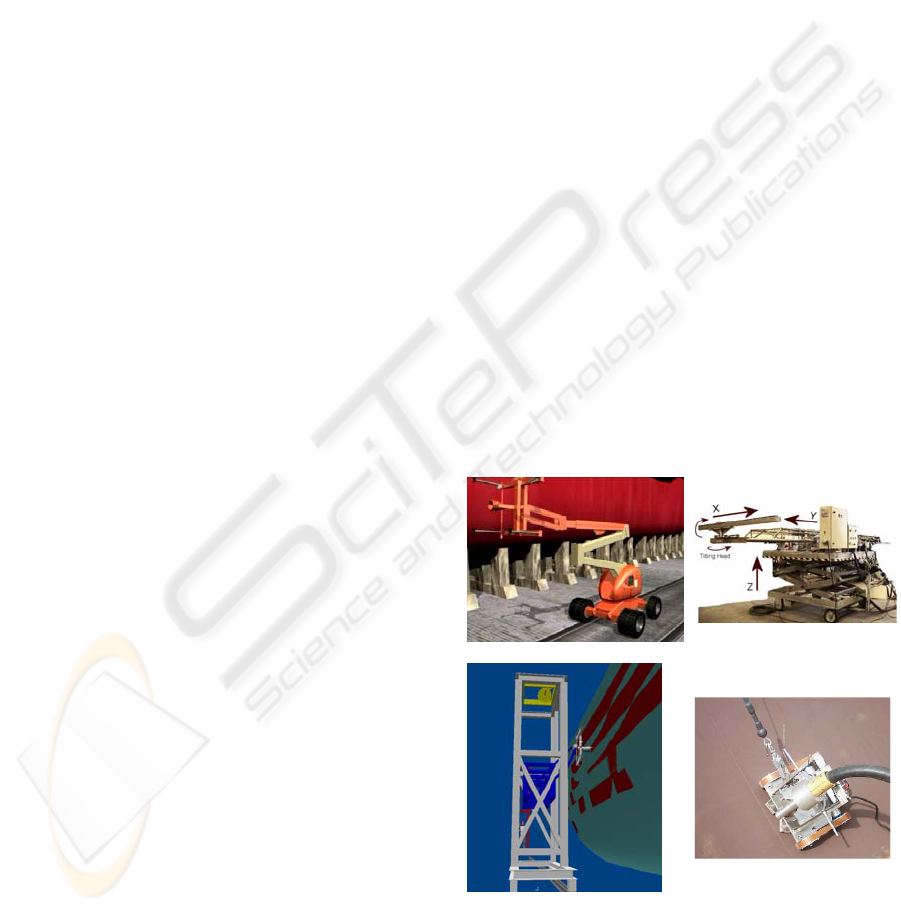
shared. EFTCoR’s robotized systems consist of a
primary positioning system capable of covering
large hull areas and a secondary positioning system
mounted on primary system that can position a tool
over a relatively small area (4 to 16 m2). Different
combinations of primary/secondary/tool have been
considered and tested (see Figure 1).
a) XYZ table & cherry-picker b) Scissor crane
c) Tower with a tool positioner d) Climbing vehicle
Figure 1: Different solutions for grit blasting
Finally, it is important to stress that the
EFTCoR is an industrial project and as such should
A REFERENCE ARCHITECTURE FOR MANAGING VARIABILITY AMONG TELEOPERATED SERVICE ROBOTS
323
use components that are common in industrial
facilities (PLCs rather than work-stations, field
buses rather LANs, etc.)
4 THE REFERENCE
ARCHITECTURE
ACROSET (Arquitectura de Control para Robots de
Servicio Teleoperados
*
) is a reference architecture
for teleoperated service robot control units. The
architecture emerged from previous works at the
DSIE (División de Sistemas e Ingeniería
Electrónica, Universidad de Cartagena, Spain)
(Iborra, 2003), (Ortiz, 2000), and is currently being
used in the EFTCoR project. ACROSET takes
account of the sources of variability explained in
sections 2 and 3 and the architectural drivers
developed to deal with them.
ACROSET is supposed to make very different
systems to use the same components, and therefore
the first step was to define the rules and common
infrastructure that would allow components to be
assembled or connected. To that end, the concepts of
components, ports and connectors were adopted as
defined in (Hofmeister, 2000). The connector
concept allows components’ functionality to be
separated from their interaction patterns, because
such patterns contained within the connectors. The
notation followed to describe the components, ports
and connectors is inspired by the 4 views of
Hofmeister (Hofmeister, 2000) and ROOM (Selic,
1994), which extend the UML notation with
stereotyped classes and special symbols (see
subsection 4.1.)
The subsystems defined by ACROSET are
shown in Fig. 2. The first subsystem of the
architecture, which should be present in every
system, is the Coordination, Control and
Abstraction Subsystem (CCAS). The CCAS abstracts
and encapsulates the functionality of the physical
devices of the system. The CCAS is composed of
virtual components which can be implemented in
either software or hardware, even considering
COTS. This subsystem breaks down into several
components distributed in hierarchical layers (see
section 4.1).
To deal with operator-driven and semi-
autonomous systems, an Intelligence Subsystem (IS)
is proposed. In this way, autonomous behaviours
*
Control Architecture for Teleoperated Service Robots.
can be added if necessary, interacting with the
functionality offered by the CCAS as another user.
This separation of intelligence and functionality
enhances the modifiability and adaptability of the
system to new missions and behaviours. The
intelligence can be combined with the operator
commands depending on the application or mode of
operation. A User Interaction Subsystem (UIS) is
proposed to interpret, combine and arbitrate between
orders that may come simultaneously from different
users of the system’s functionality (CCAS), since the
system does not concern itself with the source of the
order.
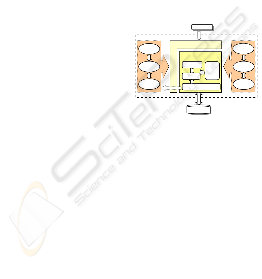
Figure 2: An overview of ACROSET subsystems
Other important aspects besides the
functionality or the intelligence of the system
include the safety and the possibilities of
configuration and management of the application.
To differentiate between functionality per se and the
monitoring of such functionality, a Safety,
Management and Configuration Subsystem (SMCS)
is proposed. Another function of this subsystem is to
manage and configure the initialization of the
application.
4.1 The Coordination, Control and
Abstraction Subsystem (CCAS)
The CCAS of a given system comprises components
that are defined in four layers of granularity:
• Layer 1: Abstract the characteristics of atomic
components, such as sensors and actuators.
• Layer 2: Simple Unit Controllers (SUCs).
• Layer 3: Mechanisms controllers (MUCs).
• Layer 4: Robot controllers (RUCs).
The simplest components modelled by the
architecture are the sensors and actuators, which are
CCAS
Users
Devices
UIS
Stra-
tegies
Coord
Control
Abstract Devices
Intellig. 1
React.
Intellig. 2
SMCS
IS
Mngment
Safety
Config
ICINCO 2005 - ROBOTICS AND AUTOMATION
324
defined at the lowest architectural level. The SUC
components model the control over the actuators
(Figure 3). For example, there will be SUCs defined
to control every joint of a given mechanism. The
SUC generates commands for the actuator according
to:
• The orders that it receives from another
component (through the SUC_Control port).
• The information it receives from the sensors.
• Its installed control policy.
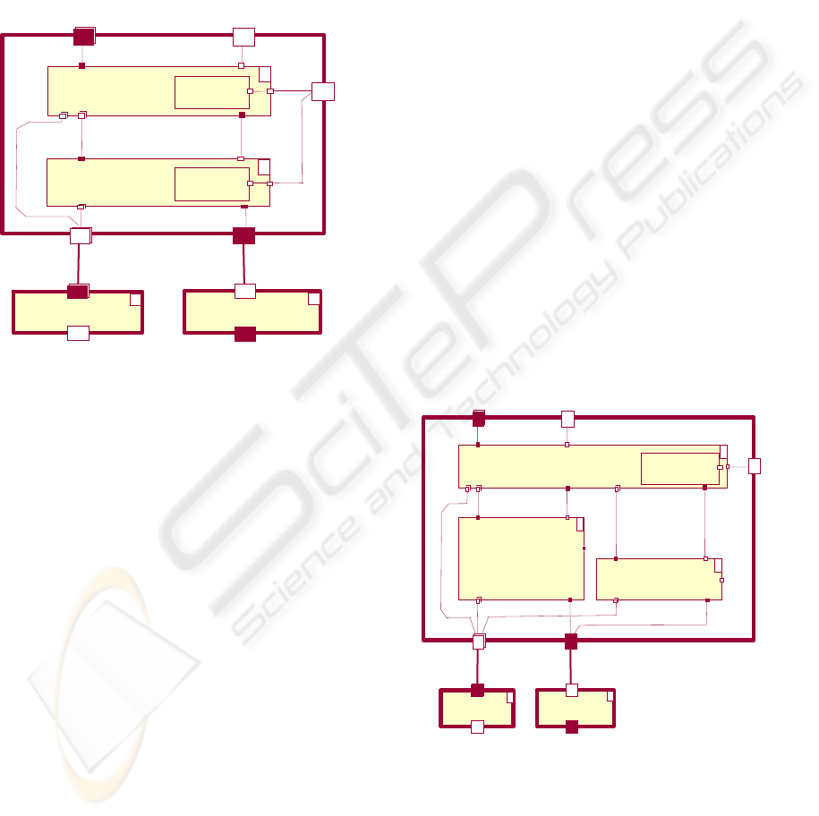
Figure 3: MUC and SUC. 1 actuator - N sensors
The control policy is an interchangeable part of
the SUC. For example, the ControlStrategy of a
given joint may be a traditional control (PID) or may
be changed for a fuzzy logic strategy. The SUCs
usually need to accomplish hard real time
requirements and are generally implemented in
hardware. Where they are implemented in software
they impose severe real time constraints on
operating systems and platforms.
Defined at the third level of granularity is the
Mechanism Unit Controller (MUC). The MUC
component models the control over a whole
mechanism (vehicle, manipulator or end effector).
As Fig. 4 shows, the MUC is a logical entity
composed of:
• An aggregation of SUCs.
• A Coordinator responsible for coordinating
SUC actions according to the commands and
information that it receives.
• Its installed coordination strategy.
The coordination strategy is an interchangeable
part of the SUC component. For example, the
CoordinationStrategy of a given manipulator may
be a particular solution for its inverse kinematics,
the coordinator strategy for a given vehicle could be
a particular navigation strategy, etc.
Although the architecture defines the MUCs as
relational aggregates, they can actually become
components (hard or soft) when the architecture is
instantiated to develop a concrete system. Whether
or not the interfaces of the inner SUCs are directly
accessible is a decision for the architecture
instantiation. In fact, although MUCs may be
implemented in either hardware or software, they
are very commonly commercial motion control
cards that constrain the range of possible commands
to its internal components. COTS elements limit the
flexibility of the approach, in the sense that they do
not always provide direct access to their inner sub-
components or to their inner state.
Finally, at the fourth level, the architecture
defines the RUC (Robot Unit Controller)
component. The RUC component models the control
over a whole robot, for example a robot composed
of a vehicle with an arm and several interchangeable
tools. As Figure 4 shows, the RUCs are an
aggregation of MUCs and a global coordinator that
generates the commands for the MUCs and
coordinates their actions, according to the orders and
the information that it receives and its installed
coordination strategy.
Figure 4: RUC: Robot Unit Controller.
This strategy is an interchangeable part of the
RUC. For example, the CoordinationStrategy of a
robot composed of a vehicle with a manipulator
could be a generalised kinematics solution that
contemplates the possibility of moving the vehicle to
strConfig
+ / MUC_Control~
Coordinator
+ / MUC_DataOut
MUC
+ / SUC_Control~
+ / SUC_DataOut
<<data>
<<data>
<<contro
l
+ / sensorDataIn~
+ / actuatorControl
+ / devDataIn~
+ / sensorDataOut
+ / actuatorControl~
+ / devControl
<<data>> <<control>>
Actuator Sensor
n
1
Strategy
1
SUC
n
Strategy
RUC_Control~
Coordinator
RUC_DataOut
RUC
MUC_Control MUC_DataOut
SUC_DataOut
SUC_Control~
strConfig
<<
data
<<data>
<<control>>
<<control>>
<<data>>
Strategy
sensorDataIn~ actuatorControl
<<data>>
<<control
>
Actuator
Senso
r
n
1
SUC
MUC
1
n
n
A REFERENCE ARCHITECTURE FOR MANAGING VARIABILITY AMONG TELEOPERATED SERVICE ROBOTS
325
reach a given target. Like the MUCs, the RUCs are
logical components that can become physical
components depending on the concrete instantiation.
In general, the RUC is quite a complex component
that comprises hardware and software components
and can expose a wide variety of interfaces
depending on the complexity of the controlled
system.
4.2 The Intelligence Subsystem (IS)
It is beyond the scope of this paper to give a detailed
explanation of the IS, but we do offer some
considerations at this point. The CCAS is well suited
to operator-driven systems and systems where the
reactive or autonomous behaviour responds to
simple rules that can be added to controllers and
coordinators. However, there are systems where the
autonomous behaviour is anything but simple. In
such cases, the intelligent component needs to
integrate more information and access more
functionality than what is embedded in a given
component. The approach adopted here is to
superimpose “intelligent” autonomous behaviour
and operator-driven behaviour, and to provide the
means of integrating both and resolving the potential
conflicts by means of “arbitration” components
which merge commands from several sources
following different strategies and provide a unique
command to the goal component. This approach
does not entail any change in the components
defined so far, but it does entail new sources of
commands for them. Such “arbitrators” permits the
goal components not to change although new
sources are introduced.
5 ACROSET INSTANTIATION
ON EFTCOR
The ACROSET architecture is being implemented
on a real system, the family of robots in EFTCoR
project. This section presents two instantiations of
the architecture. As we will see, they have been
chosen to illustrate the suitability of ACROSET for
defining the concrete control architectures of two
very different systems.
5.1 ACROSET in teleoperated XYZ table
The first instantiation of ACROSET is used for
developing the control unit of a system composed of
a XYZ table (Fig. 1. a, c) holding the cleaning tool.
This tool consists of an enclosed nozzle for making
the blasting and recovering of residues. The system
can be driven by a human operator and it can also
perform some autonomous tasks. The XYZ table is
supported by a commercial crane whose control is
not considered in this instantiation.
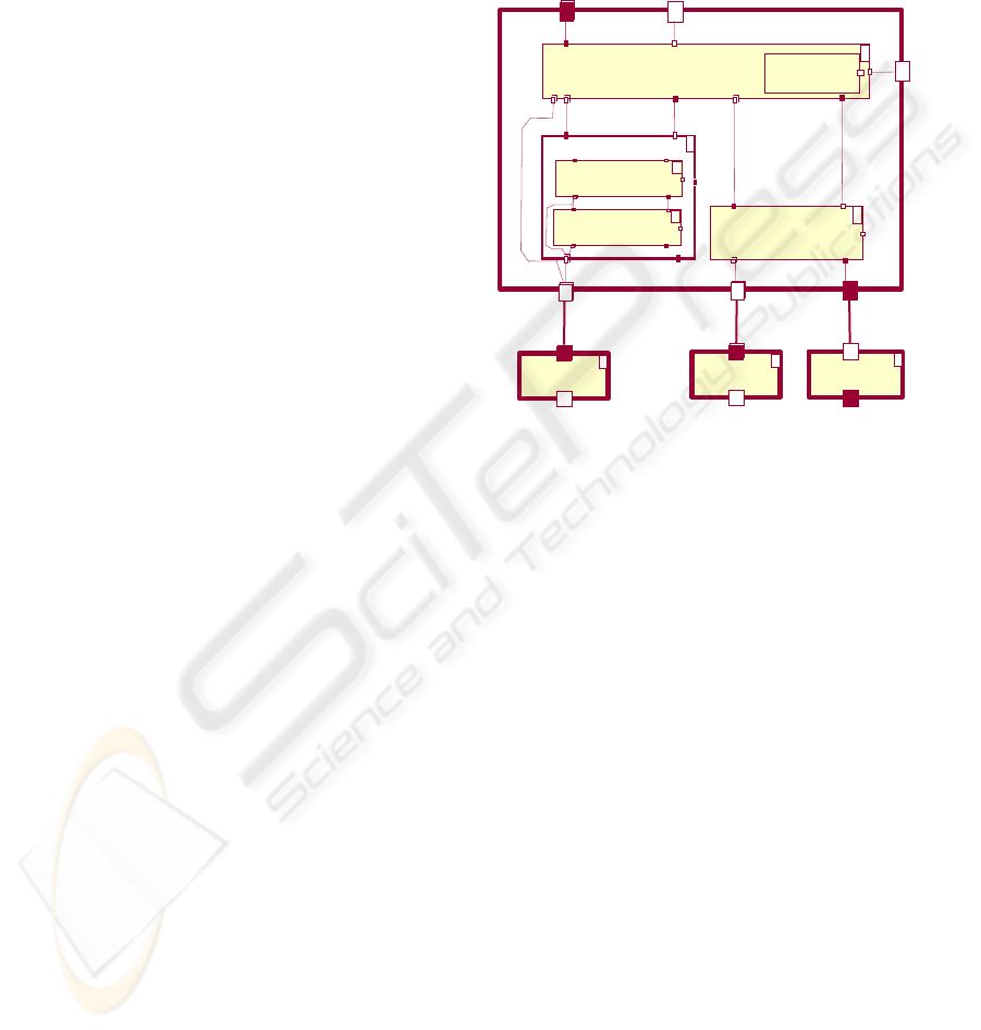
Figure 5: Components of CCAS in XYZ table Control
Unit.
The components integrated in the Coordination,
Control and Abstraction Subsystem (CCAS) are
shown in Figure 5. The RUC encloses all the
functionality required to drive the XYZ table and the
tool. The MUC and SUC included in the RUC
control the XYZ table and the blasting tool
respectively. The MUC coordinates three SUCs, one
for each axis of the table. In this case the actuators
are logically placed inside the SUCs and are
accessed through the SUC interface. This is imposed
by the system’s hardware architecture. In this case,
COTS hardware controllers have been used to
control the electrical motors of the XYZ table.
Therefore, the hardware that is abstracted is not
merely an engine but a complete axis controller. The
actuator is hidden to the control unit and the SUC is
thus a “hardware abstraction component”
contained in a MUC. The SUCs that control the axes
therefore have a software part and a hardware part.
The RUC and the MUC are implemented entirely in
software.
Following ACROSET, the intelligence of the
system, like the fault and configuration
management, is located outside the CCAS. The two
are respectively included in the Intelligence
RUC_Control~
Coordinator
RUC_DataOut
RUC
MUC_Control MUC_DataOut
SUC_DataOut
SUC_Control~
strConfig
<<
data
<<data>>
<<control>>
Strategy
sensorDataIn~ actuatorControl
<<data>>
<<control
>
eValve
switch
n
1
XYZtable:MUC
1
1
blastTool:SUC
1
<<data>>
n
switch
Axis:SUC
3
Coordinator
1
ICINCO 2005 - ROBOTICS AND AUTOMATION
326
Subsystem (IS) and the SMCS, as shown in Figure 2.
The real intelligence included in the IS varies
considerably from system to system. In this
particular case the IS interprets a pre-programmed
sequence of motions and orders that have been
generated by a vision system. The vision system is
an external system, running on a PC, that analyses
the surface to be cleaned, generates trajectories and
delivers them to the IS, which in turn delivers them
to the UIS and supervises their execution. A human
operator can supervise the movements commanded
by the vision subsystem and take corrective action
by means of a joystick. An arbitrator situated in the
UIS determines which is controlling the system at all
times (note that the CCAS only receives orders from
one channel coming from the UIS).
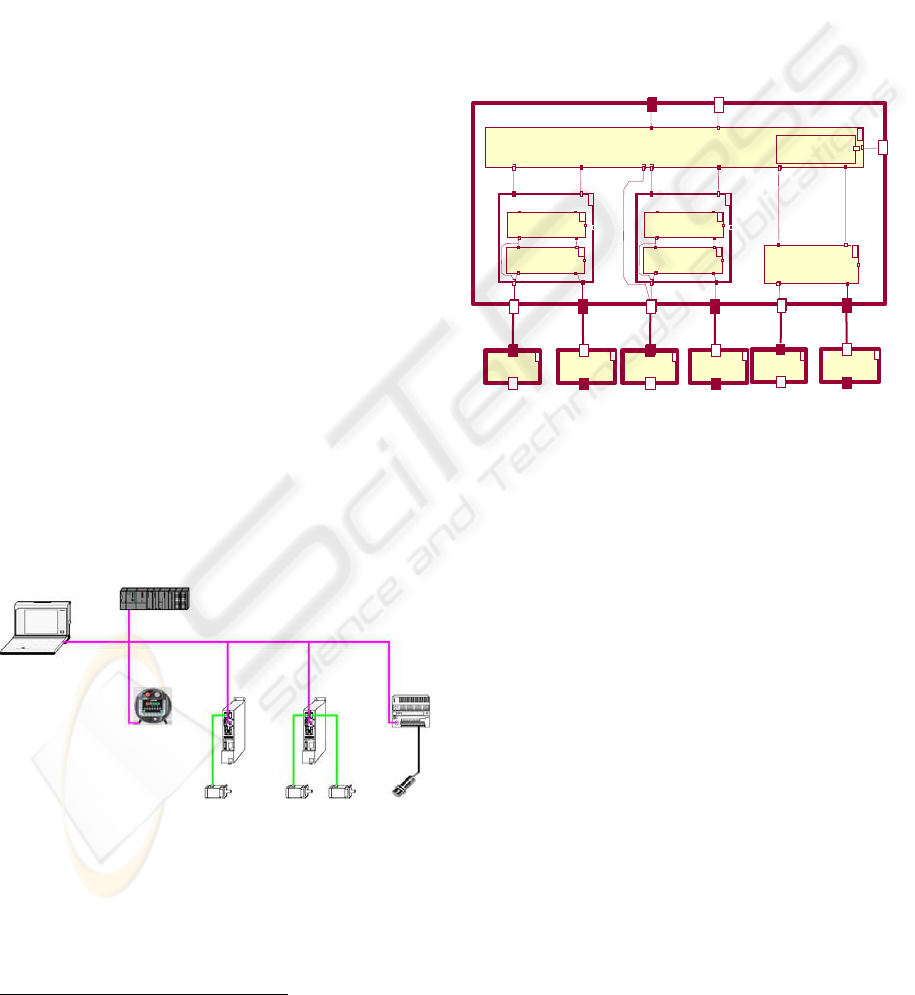
In response to the special industrial requirements
of the EFTCoR project, the system has been
implemented using a PLC
†
SIMATIC S7-300 (4 in
figure 6) and a Field-Bus (PROFIBUS-DP, 2 in
figure 6). The development environment is “STEP
7” from SIEMENS (SIMATIC, 2002). Each SUC,
MUC and RUC has been translated to PLC Function
Blocks (FBs) (SIMATIC, 2002). With the option of
FB instantiation in SIMATIC S7-300 series, it is
possible to program the PLC with a philosophy that
is close to the object-oriented paradigm (each FB
acts as a class which can be instantiated). For
instance, a generic axis controller (SUC) has been
defined to create three instances, the controllers
(SUCs) for the X, Y and Z axes, each with their
particular features. In this case, the SUCs implement
interfaces to the hardware controllers (drivers) of the
electrical motors (6 and 7 in figure 6)
Figure 6: Hardware architecture
The PLC and Field-Bus based solution adopted
is based entirely on standard industrial equipment
(SIEMENS devices interconnected via PROFIBUS-
DP), which facilitates the integrability,
†
Programmable Logic Controller
interoperability and maintainability of the complete
system.
5.2 ACROSET for a teleoperated vehicle
The second instantiation is a caterpillar vehicle
capable of scaling a hull thanks to permanent
magnets (Figure 1- d), carrying a manipulator that
holds a cleaning tool. Like the previous system, the
vehicle can be driven by a human operator and also
performs some autonomous tasks, such as obstacle
avoidance and simple path execution.
Figure 7: Components of CCAS in climbing vehicle
Figure 7 shows the CCAS instantiated for the
control unit in this system. As can be seen in the
figure, two different MUCs have been implemented:
one to control the vehicle and another to control the
manipulator. The first contains one SUC to control
each of the electrical motors that move the vehicle.
On the other side, the manipulator MUC coordinates
two SUCs, one for each manipulator axis. The
vehicle uses the same tool as the XYZ table, so this
SUC is conceptually the same, but it has been
implemented in a different way.
Unlike the previous case, the motion controllers
are not implemented by means of COTS hardware
components, but by means of Ada packages that
implement the interfaces defined by ACROSET. In
this case the implementation allows direct access to
the hardware without mediation by any SUC.
However, as in the previous case, the application has
been designed to allow either a human operator or
an external system to access the CCAS functionality
through the UIS. Two different intelligent
behaviours have been added to the IS: obstacle
avoidance and path execution. The components of
the IS that implement these behaviours obtain the
information they need from the vehicle sensors and
<<control>
>
eValve
1
RUC_Control
Coordinator
RUC_DataOut
strConfig
<<data>>
<<control>>
Strate
gy
<<data>
>
switch
1
1
1
blastTool:SUC
1
<<data>
>
2
encoder
Axis:SUC
2
Coordinator
1
1
wheel:SUC
2
Coordinator
1
<<data>> <<control>
>
eMotor
encoder
2
2
<<control>
>
eMotor
2
RUC
(1) PG/PC
(2) Field-Bus
(3) Operator Panel
(4) PLC
(5) Sensors
(6) Driver
(7) Motor
A REFERENCE ARCHITECTURE FOR MANAGING VARIABILITY AMONG TELEOPERATED SERVICE ROBOTS
327

generate commands to the CCAS. Integration
between these commands and the operator
commands is resolved by an arbitrator in the UIS.
The execution platform is an on-board
embedded PC. The PC/104 bus (PC104, 2004) is a
widely used industrial standard with many
advantages, such as vibration-resistance, modularity,
mechanical robustness, small form factor (96 x 115
mm), low power consumption, etc. Moreover, it can
be easily extended with boards that provide the kind
of functions needed by robots (digital and analogue
I/O, motion control, PCMCIA expansion, etc). The
chosen OS is RTLinux (Baravanov, 1997), with
which makes it is possible to have a real-time
application running while retaining all the power of
a Linux distribution (though with some restrictions)
underneath.
6 CONCLUSIONS AND FUTURE
WORKS
The use of a common architecture for a domain or
family of systems allows rapid developments and
the reuse of components. This paper has presented a
common architectural framework for the
development of teleoperated service robots control
units (ACROSET), and also two application
examples in the context of the EFTCoR project that
show the ability of ACROSET to cope with the
needs and requirements of very different systems.
The separation of the conventional functionality of
the systems (CCAS) from the intelligent behaviours
greatly facilitates the addition of new functionalities
and the maintenance of applications. The main
drawback is the lack of language support for
expressing a component-oriented style of
programming.
ACKNOWLEDGMENTS
The DSIE wishes to thank the Spanish Government
(CICYT) and the Regional Government of Murcia
(Seneca Programmes) for their support: TIC2003-
07804-C05-02 and PB/5/FS/02.
REFERENCES
Barabanov M.. "A Linux-based Real-Time Operating
System". Master Thesis, New Mexico Institute of
Mining and Technology, Socorro, New Mexico, June
1997.
Bruyninckx, H., Konincks, B. and Soetens, P., “A
Software Framework for Advanced Motion Control”,
Dpt. of Mechanical Engineering, K.U. Leuven.
OROCOS project inside EURON. Belgium. February
2002. Retrieved October 12, 2003 from
http://www.orocos.org
Coste-Manière, E. and Simmons, R., “Architecture, the
Backbone of Robotic System”, Proc. of the 2000
IEEE International Conference on Robotics &
Automation, San Francisco, April 2000.
EFTCoR - Environmental Friendly and Cost-Effective
Technology for Coating Removal. V Framework
Program GROWTH G3RD-CT-00794. 2002-2005
Gamma E., Helm R., Johnson R., Vlissides J., “Design
Patterns: Elements of Reusable Object Oriented
Software”, Addison Wesley, Reading Mass. 1995.
Hofmeister, C. Nord, R., Soni, D., “Applied Software
Architecture”, Addison-Wesley. ISBN 0-201-32571-3.
USA. January 2000.
Iborra, A. Pastor, J.A., Álvarez, B. C. Fernández and
Fernández-Meroño J. M., “Robots in Radioactive
Environments”, IEEE Robotics and Automation
Magazine, vol. 10, no. 4, pp. 12-22, December 2003.
Nesnas, I. et al, “CLARAty: An Architecture for Reusable
Robotic Software”, Jet Propulsion Laboratory, NASA,
Carnegie Mellon University, March 2003.
Ortiz, F.J. et al “GOYA: A teleoperated system for
blasting applied to ships maintenance”. 3rd
International Conference on Climbing and Walking
Robots. CLAWAR´2000. October, 2000.
Scholl, K.U. Albiez, J. and Gassmann, B. “MCA – An
Expandable Modular Controller Architecture”,
Karlsruhe University, Germany, 2001.
Selic, B. Gullekson G., Ward P.T., “Real-Time Object-
Oriented Modeling” (ROOM). John Wiley and Sons,
New York. 1994.
SIMATIC - Working with STEP 7 5.2. ref. 6ES7810-
4CA06-8BA0. SIEMENS manuals. 2002.
PC104. Retrieved May 1, 2004, from
http://www.pc104.org
ICINCO 2005 - ROBOTICS AND AUTOMATION
328
