HIGH TEMPERATURE DENSITY MEASUREMENT CELL WITH
A PCMCIA-INTERFACE
Bernd Eichberger
Graz University of Technology, Department of Electronics, Inffeldgasse 12, 8010 Graz, Austria
Anton Scheibelmasser
CAMPUS 02, University of Applied Sciences, Automation Technology, Körblergasse 111, 8021 Graz, Austria
Keywords: Density-Measurement, PCMCIA, File-Mapped I/O.
Abstract: One of the most precise and reliable measurement methods for density measurement of liquids and gases
depends on the principles of a mechanical oscillator. With this method the density is determined by
measuring the natural frequency of the oscillator. Measurement devices using this method can be
categorized in two groups. The first type incorporates the mechanical oscillator in the housing of the device
and is mainly used in laboratories. The second type of measurement devices could be defined as evaluation
units, because the sensor e.g. mechanical oscillator is external and only connected by means of electrical
connections. These types are used in the field of process data control or data acquisition. The reason for
separating the sensor from the evaluation unit lies in the fact that such external cells are used on remote
locations in the process or the sensor is exposed to extreme physical conditions (e.g. high pressure, high
temperatures). The first part of this article gives an overview about the functionality of such a high
temperature measurement cell. The second part of this paper is intended to introduce a sophisticated
PCMCIA interface which acts as an interface between the external density measurement cell and several
hosts like PCs, PDAs or modern density measurement devices.
1 INTRODUCTION
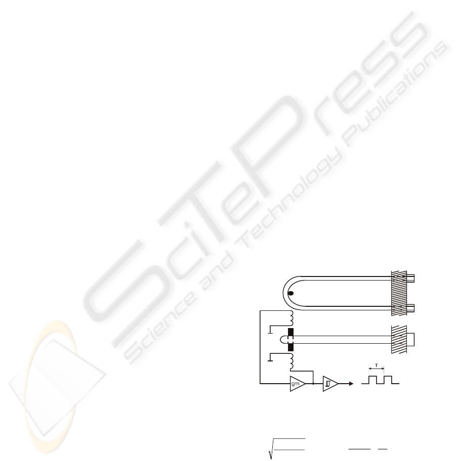
The sensor principle used in this application
converts the density of a liquid into the period of an
oscillating mechanical resonator. A U-shaped tube,
whose open ends are mechanically mounted on a
solid base plate, is filled with the liquid. For exciting
this mechanical fork oscillator a periodic excitation
force is applied, which is in opposite phase to the
speed of movement of the tubes, thus compensating
the mechanical damping force. The electrical
excitation system consists of a speed sensor, a
limiting amplifier and an actuator for mechanical
feedback. (see Figure 1)
Both the mass M of the tube and the mass
ρ
.V of
the liquid inside as well as the spring constant c of
the tube determine the resonant frequency f and its
inverse, the period T, according to equation 1. Re-
arranging this relationship results in equation 2,
which is the basis for the subsequent numerical
calculations.
Figure 1: Mechanical fork oscillator (Leopold, Eichberger,
1993)
Equation 1: Period of the fork, Equation 2: Density
The frequency of the mechanical oscillator, which is
output as a binary voltage or current signal, is
measured using a high resolution counter and a
c
VM
T
.
2
ρ
π
+
=
c
M
V
T
−=
..4
2
2
π
ρ
316
Eichberger B. and Scheibelmasser A. (2005).
HIGH TEMPERATURE DENSITY MEASUREMENT CELL WITH A PCMCIA-INTERFACE.
In Proceedings of the Second International Conference on Informatics in Control, Automation and Robotics - Signal Processing, Systems Modeling and
Control, pages 316-319
DOI: 10.5220/0001158003160319
Copyright
c
SciTePress
precise and stable reference oscillator. As standard
PCs or PDAs do not have the capability to handle
such a signal directly, considerations about how to
incorporate such an interface have to be taken (see
chapter 3).
2 THE HIGH TEMPERATURE
MEASUREMENT CELL
Density measurement at temperatures up to 400 °C
significantly increases the useful range of
applications, for example in the fields of material
research or the petroleum industry. Normally, the
mechanical resonator is mounted inside the housing
of the instrument, together with its electrical
interfaces and a microprocessor control unit.
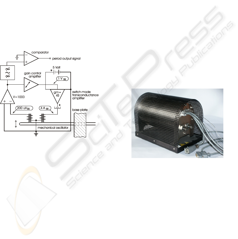
Figure 2: Excitation amplifier (Leopold, Eichberger, 1993)
Due to the demanding ambient conditions an
external measurement cell design was implemented.
The system can operate as a stand-alone unit or be
placed in a temperature-controlled oven. It consists
of a mechanical fork oscillator, PT100 temperature
sensors and an optional set of electrical heaters. The
electrodynamic excitation uses two AlNiCo
magnets, mounted on the moving end of the fork
resonator, which dip into pick-up and drive coils.
These coils are made of five turns of steel wire and
attached to a ceramic insulator. An interface box,
located nearby and operating at normal ambient
temperatures, performs the basic hardware interface
functions. The period of the mechanical resonator,
temperature data and the power control of the
heaters are transmitted or received in a digitally
encoded format. Figure 3 gives a functional
overview of the excitation system. Four amps of
drive current deliver only 200 micro volts from the
feedback coil, causing stringent requirements on the
analogue signal processing circuitry. The amplitude
of the mechanical resonator is regulated by a gain
controlled amplifier. A band-pass filter and a
comparator provide a precise period output signal.
3 EXTERNAL CELL INTERFACE
External cells most often use a frequency output
voltage or current loop (0-18mA) to enable
evaluation units to determine the density. In contrast
to Lab-Density-Meters, were the frequency signal
from the internal cell is directly evaluated by a
microcontroller, external cells require an electronic
interface to convert the analogue signal in digital
values. Such an interface consists of a power supply,
an additional microcontroller, a separate housing and
communication lines for transmitting a standardized
protocol. Figure 4 shows the high temperature cell in
its housing. The shielded tubes contain the electrical
connections for the excitation system, two PT100
temperature sensors and AC-powered heaters.
Figure 3: External high temperature density measurement
cell (Anton Paar GmbH, 2005)
In order to achieve an economical solution,
efforts were made to reduce the complexity of the
system and to lower the components count. Finally,
the best compromise was achieved by using a
PCMCIA interface.
3.1 PCMCIA Interface
PC Cards (PCMCIA, 1998), were the first
generation of credit card sized cards, introduced in
the late 1980s. The cards provide 68 pins for
electrical connections. In general, PC-Cards are
either available as memory cards in several
HIGH TEMPERATURE DENSITY MEASUREMENT CELL WITH A PCMCIA-INTERFACE
317
technologies (ROM, RAM, FLASH), or as I/O cards
(ATA disk-drives, network/modem-, or interface-
cards). Depending on the card’s thickness, PC-Cards
are available in 3 different mechanical types ( Type:
I, II, II) in the range from 3.3, 5 to 10.5 mm.
Independent from the card’s technology, the
characteristics of the card are described in a special
memory area on the card, called CIS (card
information structure).
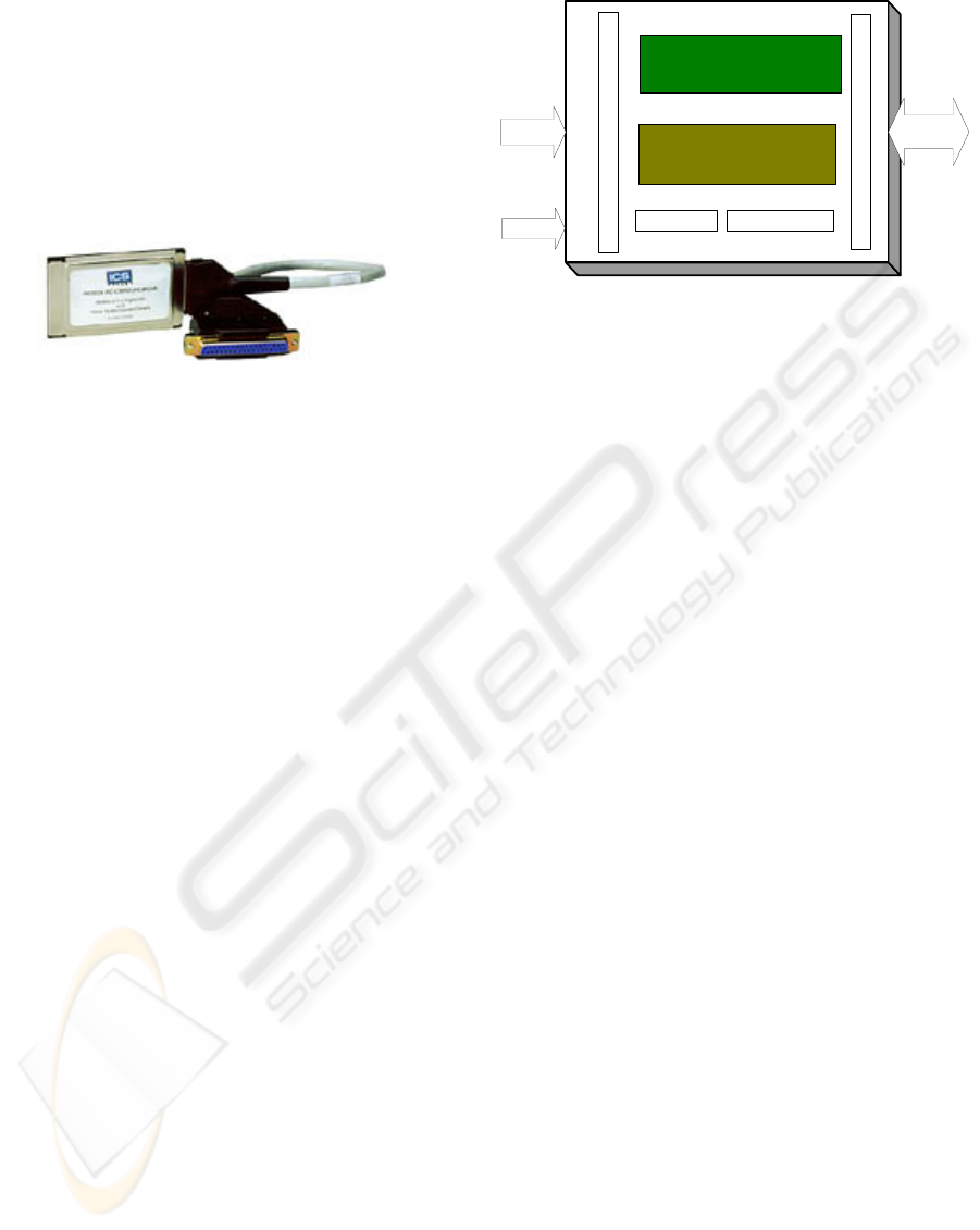
Figure 4: PCMCIA I/O card (Kontron,2005)
Typically, cards only contain Flash devices and a
rudimentary control circuit. As the card is powered
by the host, no separate power supply is needed. The
card kits (housing) are available from different
vendors with the necessary plugs and shielded
cables. Card kits provide a low cost, high quality
housing for electronic circuits. Because of the long
availability on the market, most of the laptops and
PDA (personal digital assistant) are equipped with a
PC-Card slot. Even modern laboratory density
meters provide the user with such slots.
3.2 Cards Control Circuit
The main task of the card’s control circuit is the
precise determination of the oscillator frequency of
the mechanical fork resonator. Therefore the signal
has to be converted into a binary logic signal which
is compared with a precise high frequency crystal
time base The digital output of this circuit (gated
timer without termination error) has to be stored in
data registers which are accessible from the host
with the standardized PCMCIA interface.
The realisation of the digital circuitry using a CPLD-
technology (complex programmable logic devices)
offers a lot of advantages. CPLDs offer the user the
flexibility of programming them in the field (ISP) by
means of a JTAG-interface. Low power
consumption, less PCB (printed circuit board) area,
high integration and high level programming support
(VHDL, ABEL) are good arguments for the use of
these devices.
Figure 5: Block diagram of the PC-Card interface
3.3 PLD Logic
The control logic (Röhrer,1989) implemented in the
CPLD fulfils the following requirements:
− Counting of the period signal based on a stable
and high precision reference crystal oscillator
− Storing of counter results after a selectable gate
time (1, 2, 4, 8 sec.) with an additional identifier
− Consecutive measurements, no termination error
− Implementation of data register for the
intermediate results, accessible from the host via
the PCMCIA interface
− Implementation of a command register (average
time register)
− Generation of the chip select signals for
additional Flash storage memory on the card.
For the implementation of these requirements, HDL-
Tools (hardware description language) capable for
many languages (VHDL, ABEL, VERILOG) are
available from different vendors. Typically, the
required tools are provided by the vendor of the
CPLD.
3.4 PC-Card Structure
The logic circuits in the CPLD and the additional
Flash Storage memory on the PC-Card are
implemented according to the following memory
map:
PERIOD
SIGNAL
PCMCIA
SIGNALS
CURRENT TO DIGITAL LOGIC CONVERTER
PCMCIA INTERFACE
CRYSTAL OSZILLATORJTAG INTERFACE
JTAG
CPLD
FLASH STORAGE
ICINCO 2005 - SIGNAL PROCESSING, SYSTEMS MODELING AND CONTROL
318
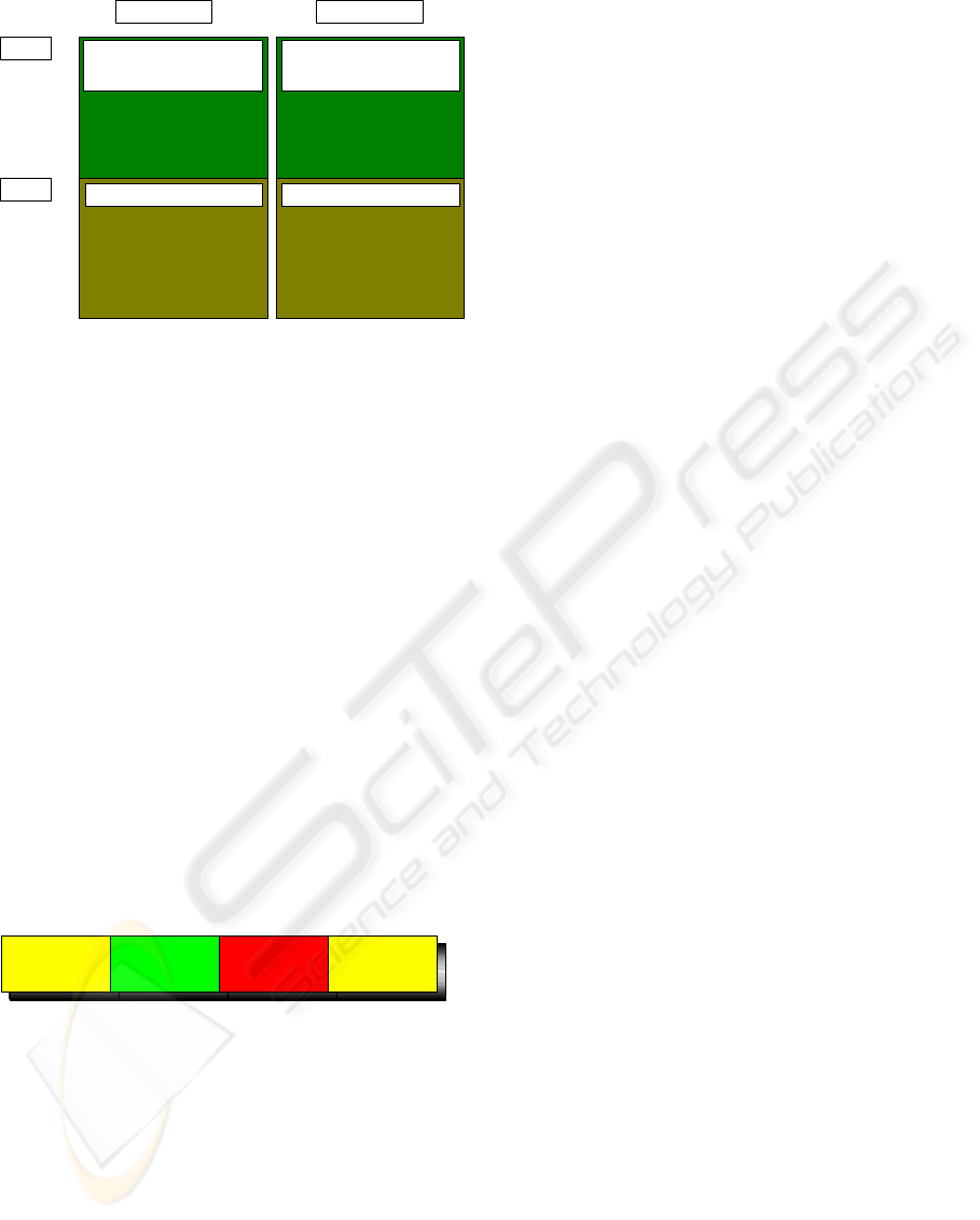
Figure 6: Memory mapped I/O card
As shown in Figure 6, the PC-Card is designed as a
memory card with an address range of 64 kByte In
the lower part of this range, the built-in flash
memory is selected and provides two types of
information. The first, called Attribute Memory,
enables the PC-Card to be used in combination with
an operation system. A special data structure (CIS,
Card Information Structure]) located at the address:
0x0000 describes the card’s characteristics in a
standardized way (PCMCIA, 1989). One of the
characteristics of this PC-Card is the command
register at the location: 0x80000, which is used to
set the gate time of the period measurement. The
second kind of information is placed in the common
memory address area. An optional file system
located at the address which is defined in the
attribute memory can be used to store additional
information (see chapter 4.5). Above the address:
0x80000, an eight-byte data structure stores the
measurement results. Details of the structure are
shown in Figure 7.
Figure 7: Data structure of the period measurement
Every time a measurement cycle is completed, the
identifier is automatically incremented. The result of
the measurement is calculated by dividing the period
counter by the clock counter. Synchronization of the
reading and the measurement logic is done by
evaluation of both identifiers. Only if these
identifiers are equal, the data structure is accepted to
be consistent.
3.5 Software Interface
A PC-Memory-Card type was developed for this
application. Such cards do not require specialized
software drivers, because they are detected correctly
by modern operating systems. Access to the memory
mapped data registers is implemented using a file-
mapped-I/O method. A special file image is placed
in the Flash-Storage with a total length of 0x80000
Bytes. In this image the last file in the directory
structure is not a real, but a virtual data file. Within
the FAT (File Allocation Table) the content of this
virtual file is linked to the data registers in the CPLD
outside the Flash-Storage area. The software running
at the host computer can now easily access the
measurement data by issuing a read command to this
file. Calibration data and parameters as well as
customer specific algorithms are stored at the host.
The application program uses this additional
information to calculate the density from the
measurement data.
The remaining files on this image are real data
files. They hold the necessary information
concerning the PC-Card (documentation, evaluation
program etc.).
4 CONCLUSION
The application of the described PC-Card-Interface
shows excellent results in the field and offers for the
evaluation of external density cells a convenient
solution which is capable to interact with PCs,
PDAs, modern laboratory density meters and
evaluation units (Anton Paar GmbH, 2005). The PC-
Cards CIS informs the host about the file system and
is therefore mapped as an exchangeable volume
without the need of special drivers. Due to the file-
mapped I/O structure, only simple file access is
required to get the measurement data.
REFERENCES
Leopold, H., Eichberger B., 1993, Ein Sensor für die
Dichte heißer Flüssigkeiten, Tagung Mikroelektronik,
Berichte der Informationstagung ME 93, Pages 102-
106, VDE-Verlag, Wien
Röhrer, R., 1989, Proceedings on the 2
nd
intensive course
on : „Programmable Logic Device“, pp.91-132, Cluj-
Napoca, Romania
Anton Paar GmbH, 2005, www.anton-paar.at
Kontron, 2005, www.kontron.com
PCMCIA, 1998, Personal Computer Memory Card
International Association, www.pcmcia.org
FLASH FLASH
CPLD CPLD
COMMON MEMORY
ATTRIBUT MEMORY
0x80000
0x00000
optional FILE Structure
optional CIS (Card Information
Structure)
DATA REGISTER COMMAND REGISTER
Identifier_1
(1 Byte)
Period Counter
(2 Byte)
Clock Counter
(4 Byte)
Identifier_2
(1 Byte)
HIGH TEMPERATURE DENSITY MEASUREMENT CELL WITH A PCMCIA-INTERFACE
319
